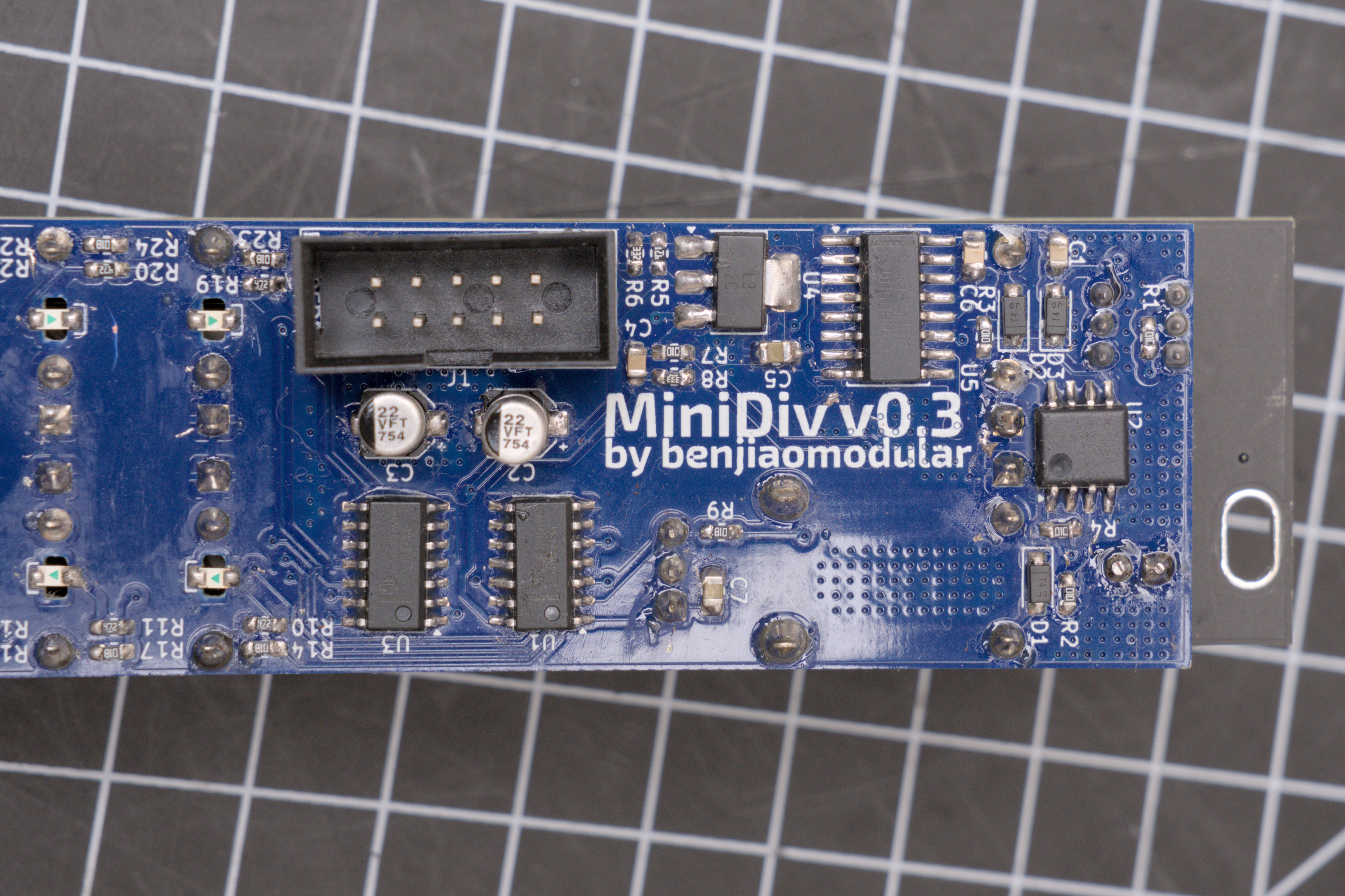
MiniDiv
Last year, I released a post about a clock divider build based on HAGIWO’s clock divider module. Towards the end of that article and the Youtube video that went with it, I talked about designing a PCB.
It took me over a year to get to it, but I finally did it!
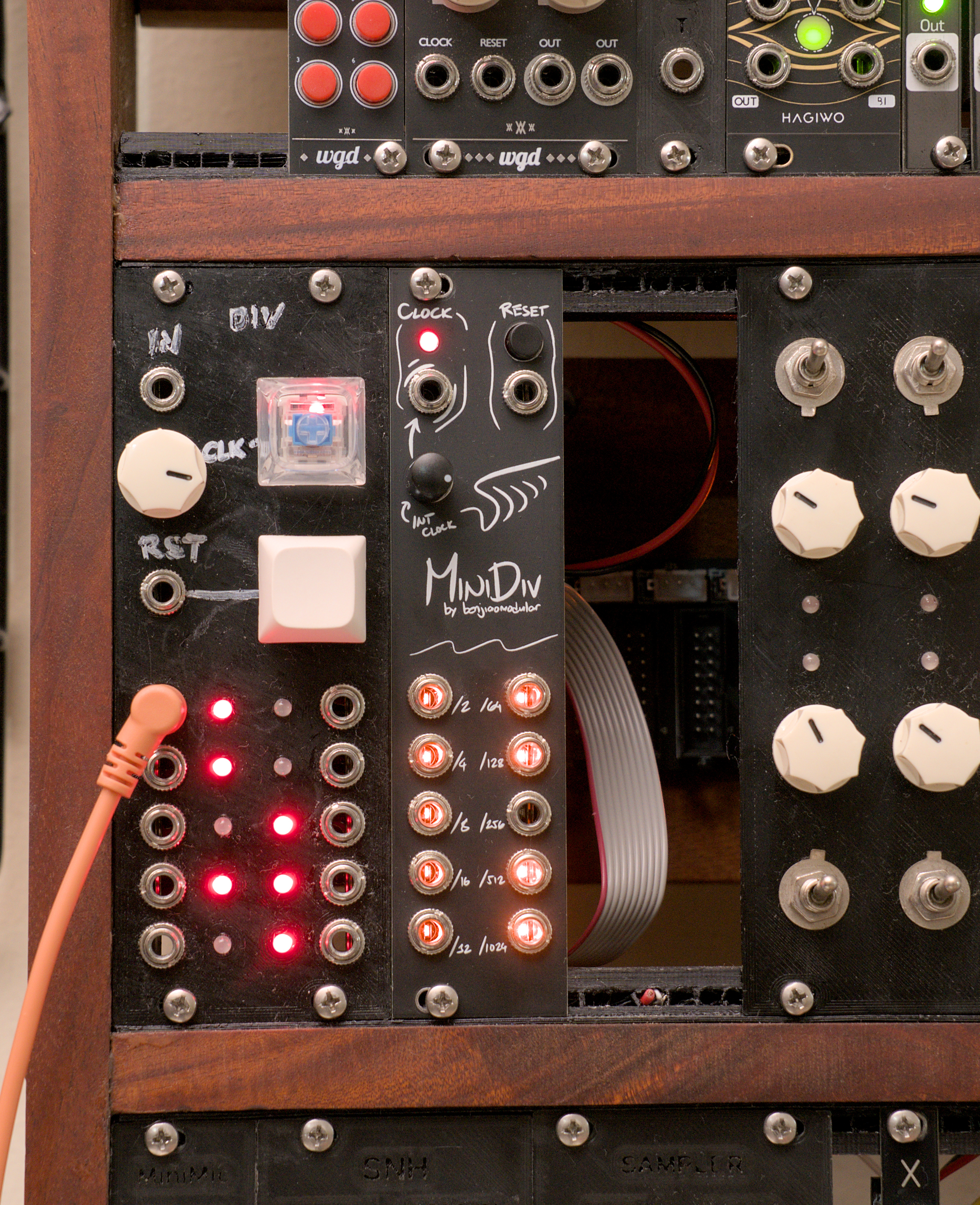
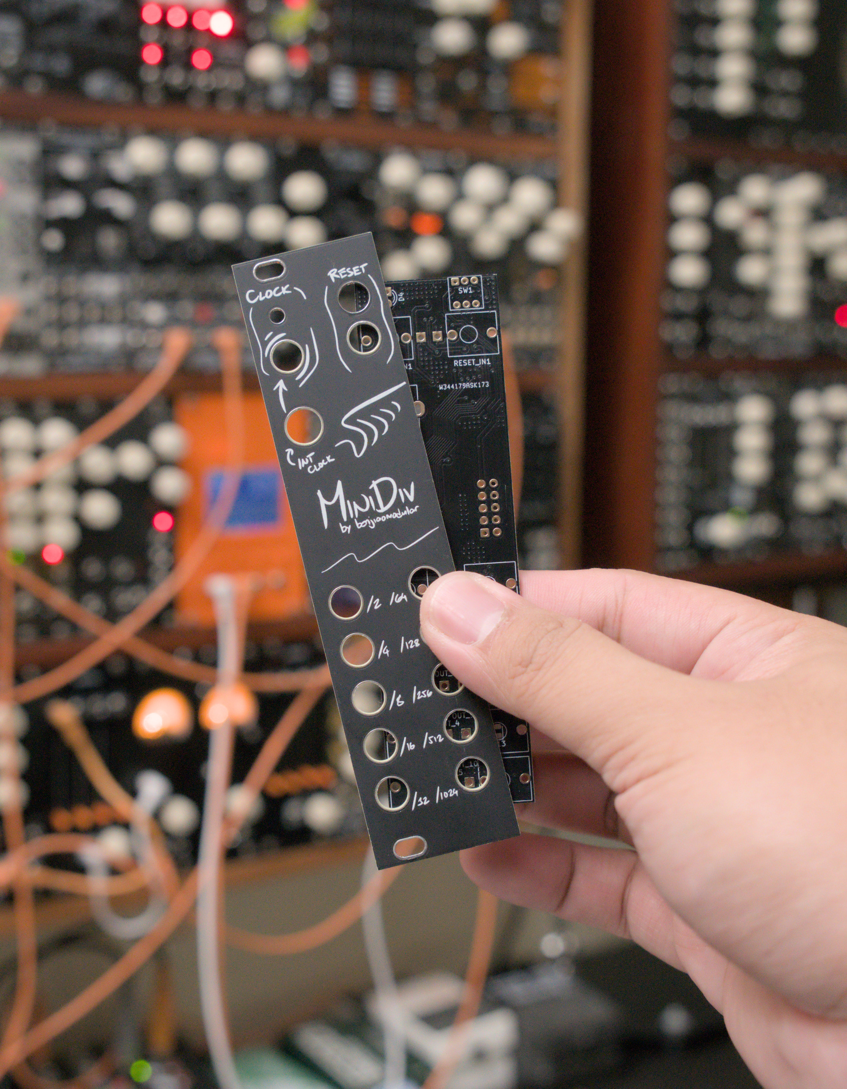
The new design comes with the same number of outputs. I included an internal clock as well as a reset input with a manual reset button.
I always like to try something new on every build. This one’s my first time trying to place LEDs under jacks. I used 0805 SMT LEDs. I think the result looks great.
It wasn’t too difficult to put together either.
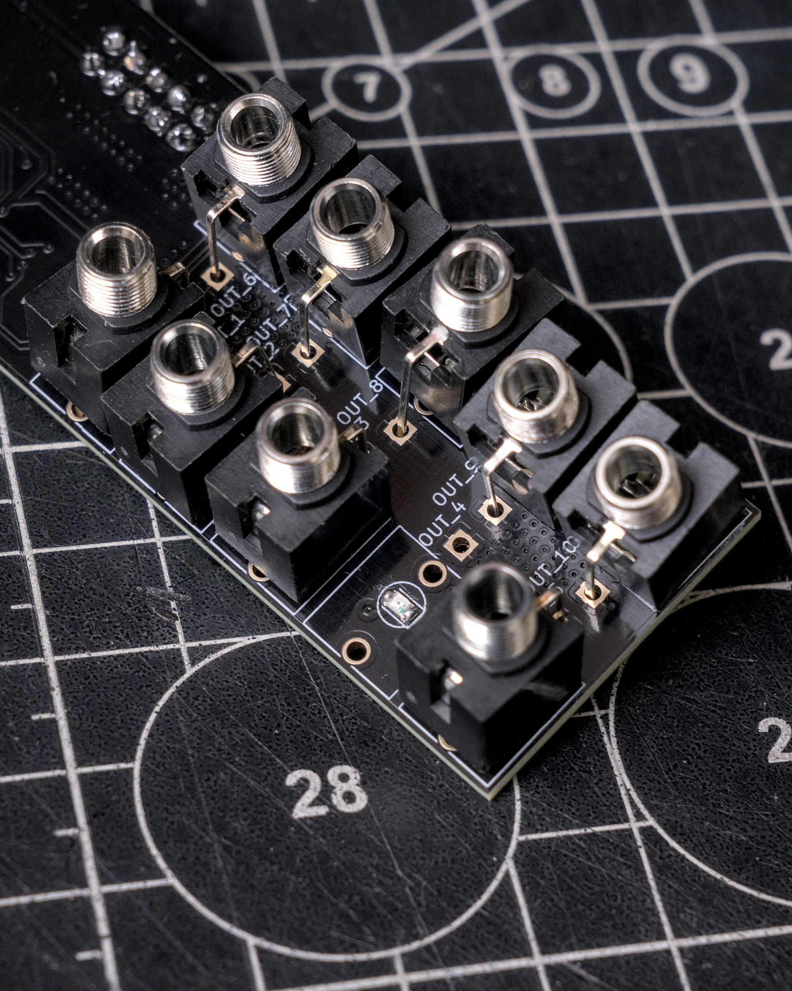
You’d obviously loose the indicator once you’ve plugged a cable in, but I’m sure I can use this technique in another build. Feel free to not include LEDs if you’re not a fan, of course.
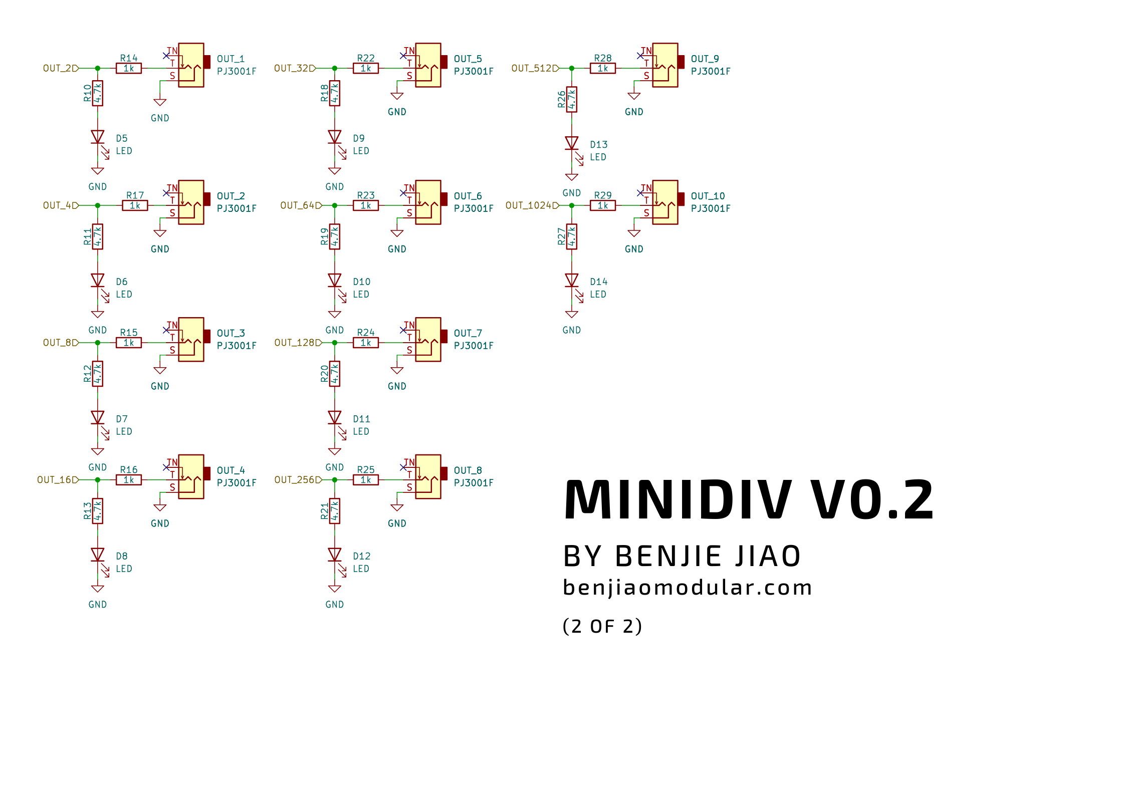
Schematics
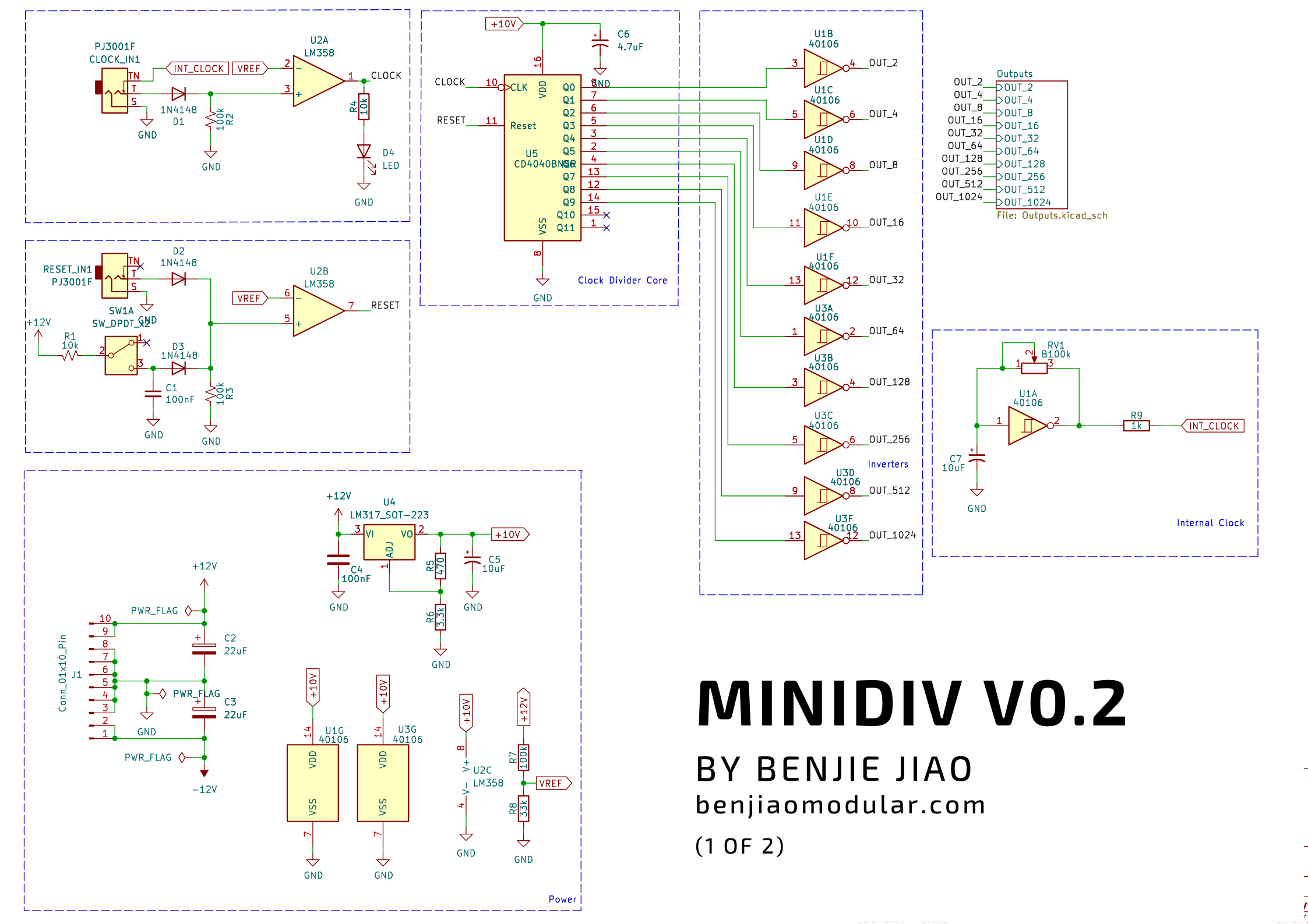
In this build, I decided to use a LM317 regulator to control fed into the CD4017. This will dictate the voltage level of each output pulse. The default configuration will put out 10V pulses.
You can adjust R5 or R6 to change the output level. You can use a calculator like this one to compute the resistor values you’ll need. In hindsight, this could probably be a trim pot.
PCB
My PCBs for this module were sponsored by PCBWay. But as always, everything’s open-source, so you can download all my files and modify/print them as you please.
About the LEDs
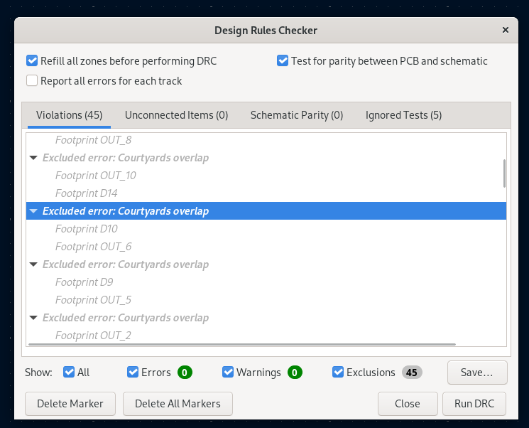
I just used separate footprints for the LEDs with the jacks, so expect KiCAD to throw an error about overlapping footprints in the DRC.
UPDATE: I’ve found a clearance issue with the LEDs under the sockets. After some investigation and testing, I noticed that the jacks would hit the LED when plugged in. The module still works, but this might cause problems down the road. I’ll do another version with a fix if you want a more reliable build.
UPDATE 2: Clearance issue was fixed in version v0.3
Links
| Title | Filename |
|---|---|
| Gerber Files | MiniDiv v0.3 - Main.zip |
| MiniDiv v0.3 - Front.zip | |
| BOM | MiniDiv v0.3 - Bill of Materials |
| Github | https://github.com/benjiaomodular/MiniDiv |
Version Log
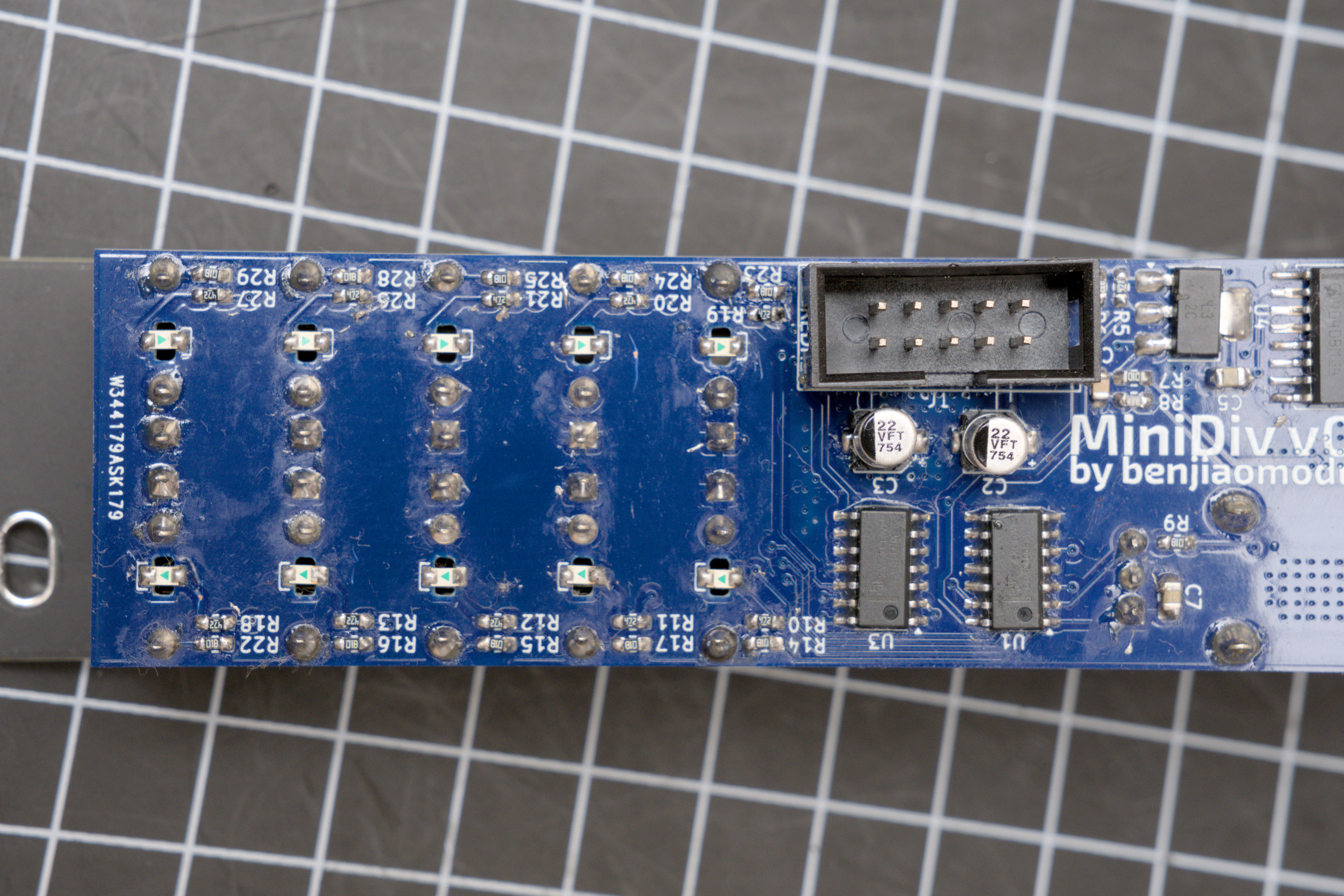
v0.3 - Moved LEDs to the back
- To address LED clearance issues, I moved the LEDs to be mounted to the back, facing down, such that the LED shines through a hole on the board.
v0.2 - Initial release
- First working version
- The LEDs were preventing the jacks from going in completly. The module still works but it might cause problems in the future.
Conclusion
Let me know if you’ve built it. Tag me on Instagram @benjiaomodular. I also have a couple of demos there!
If you’d like to support what I do, please consider donating through my ko-fi page!
More Images
