EuroPowerBoard
Introduction
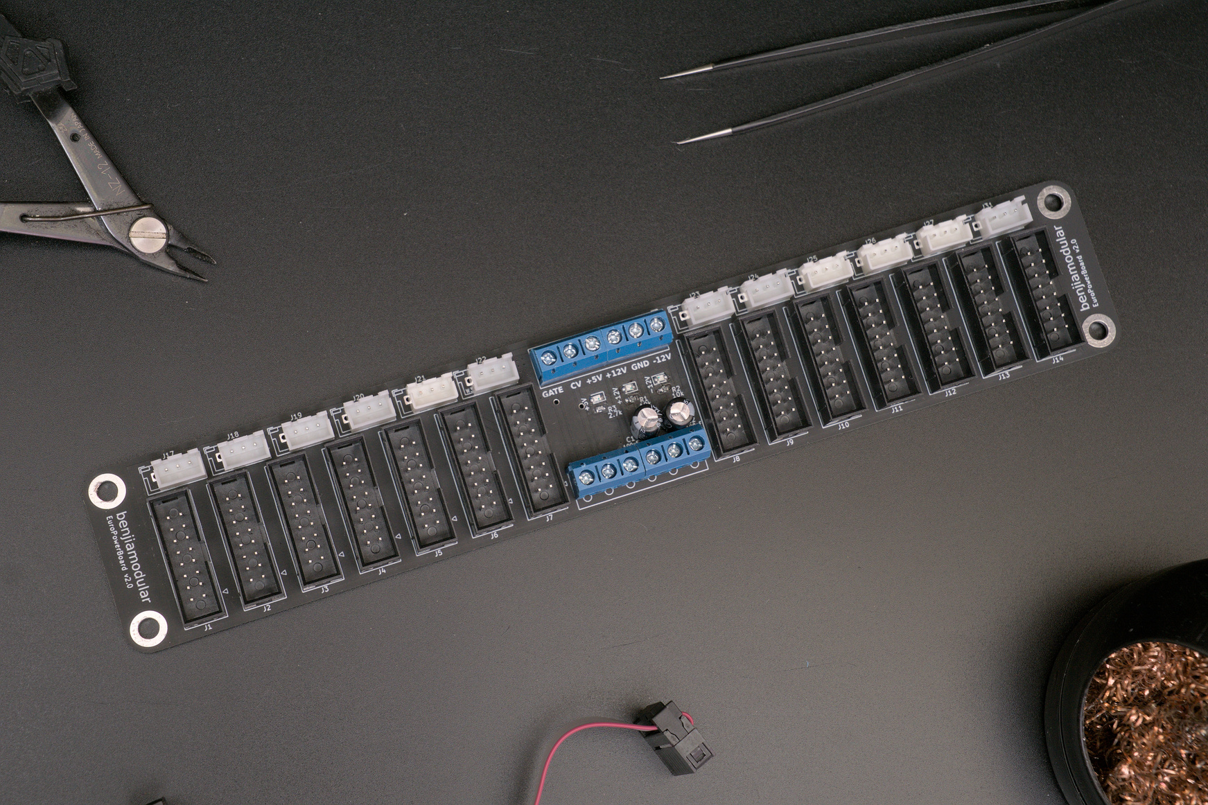
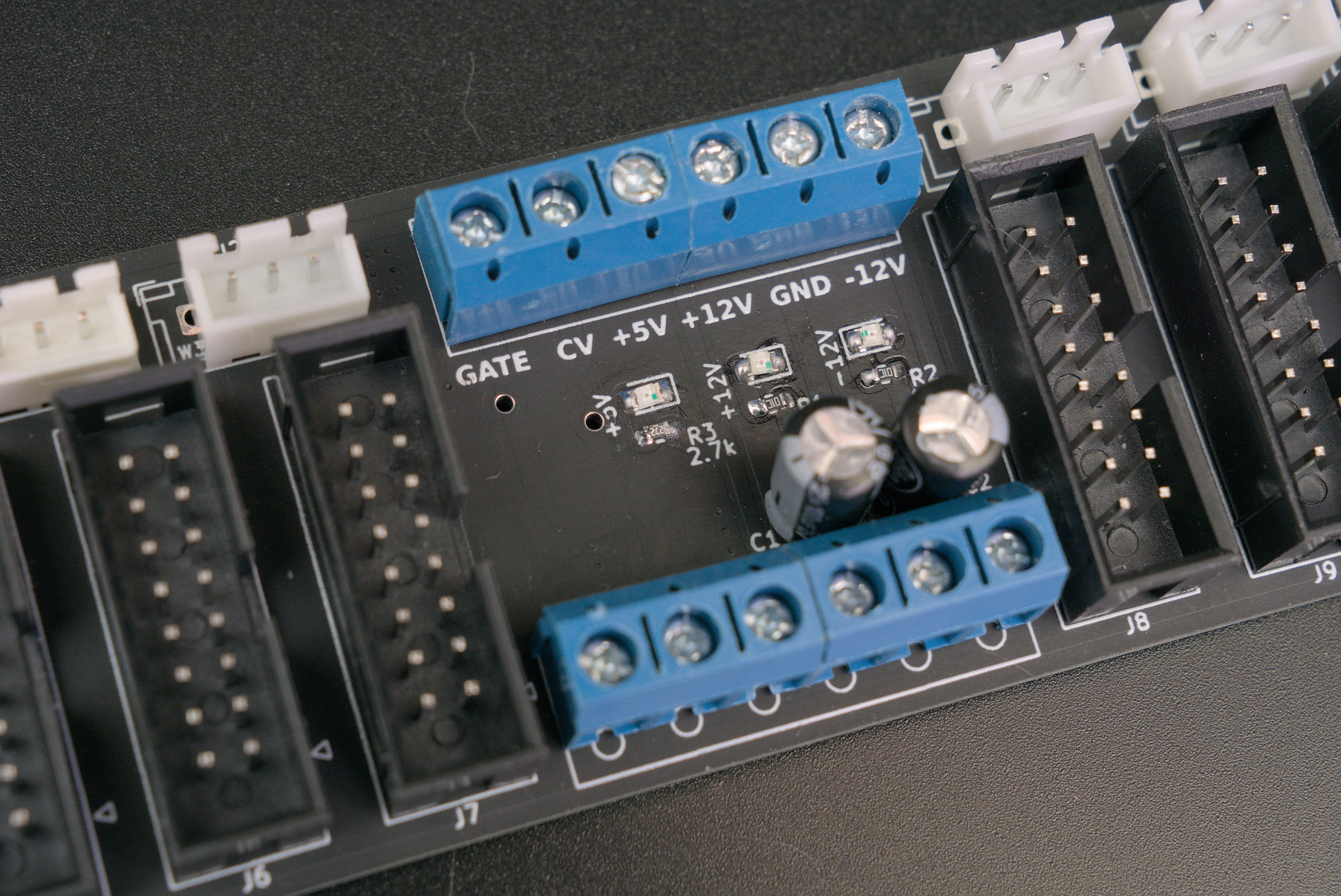
This is a busboard for Eurorack synths but with a modification for my own builds.
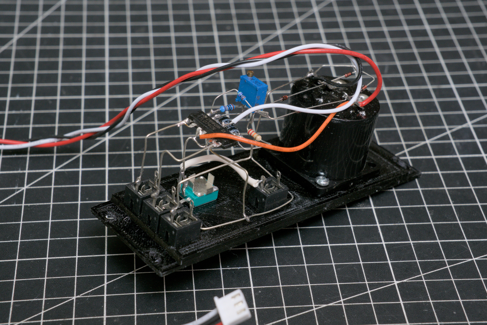
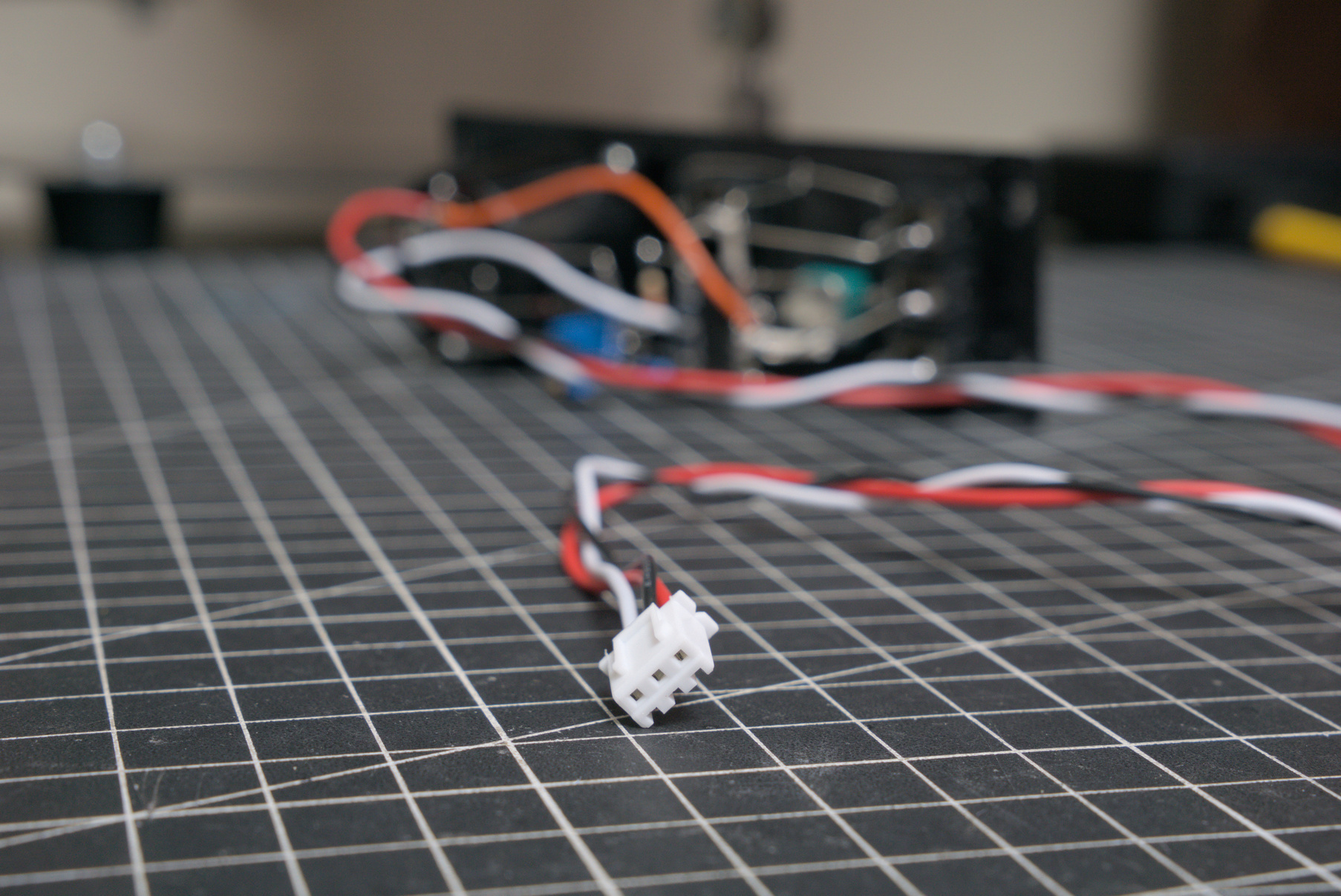
I use 4-pin JST connectors to power my deadbug builds because I find them easier to wire up without a perfboard or PCB to support a socket. I would solder wires directly to my circuit and then crimp a header to the other ends.
To accommodate modules built using this method, I added a row of JST headers to each breadboard. I still keep the 16-pin IDC headers for my more standard Eurorack modules.
This project has gone through a couple of major iterations already: (1) JST-only, (2) IDC-only, and finally (3) JST and IDC.
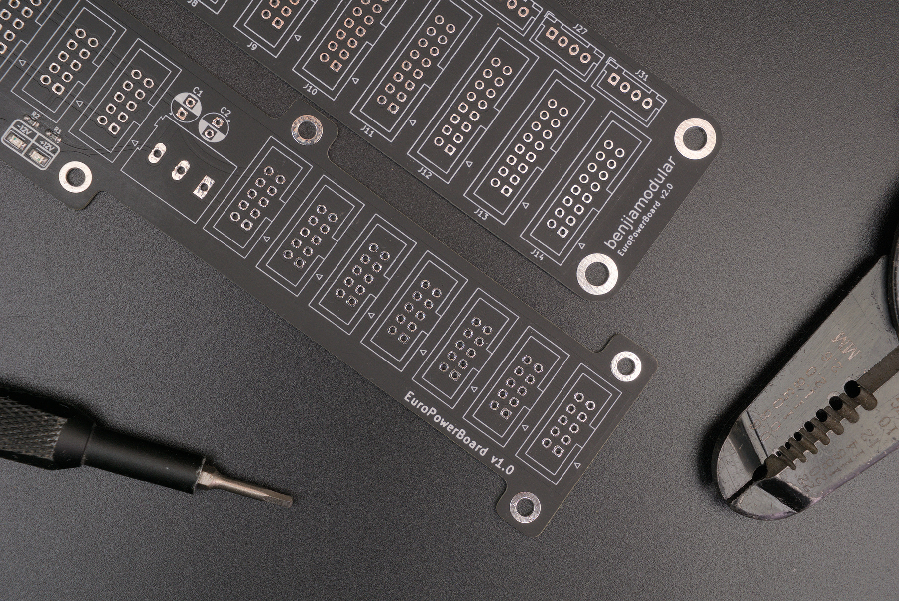
PCB
My PCBs in this series were sponsored by PCBWay – a great option for prototyping. Use their Quick-order PCB tool to get an instant quotation on the files.
PCB shops use Gerber files for etching copper traces, printing labels, drilling holes, and other manufacturing steps. You can download my zipped Gerber files for a version you like and upload those into their website.
Versions
v2.0 - Complete revamp
Now supports both 4-pin JST and 16-pin IDC connectors
| Title | Filename |
|---|---|
| Gerber Files | EuroPowerBoard v2.0.zip |
| BOM | EuroPowerBoard iBOM |
v1.0 - Original Eurorack-only version
Supports 10-pin IDC connectors
| Title | Filename |
|---|---|
| Gerber Files | EuroPowerBoard v1.0.zip |
| BOM | EuroPowerBoard iBOM |
Conclusion
Follow my Instagram @benjiaomodular for updates.