SynthCard
Introduction
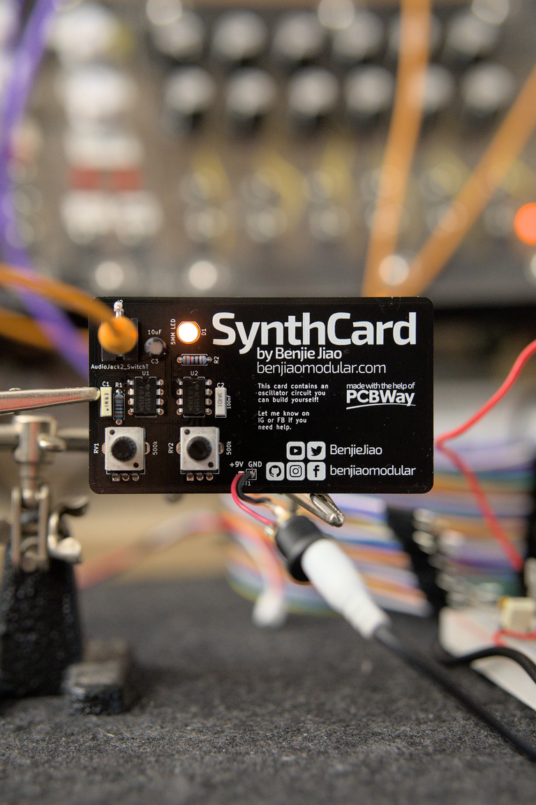
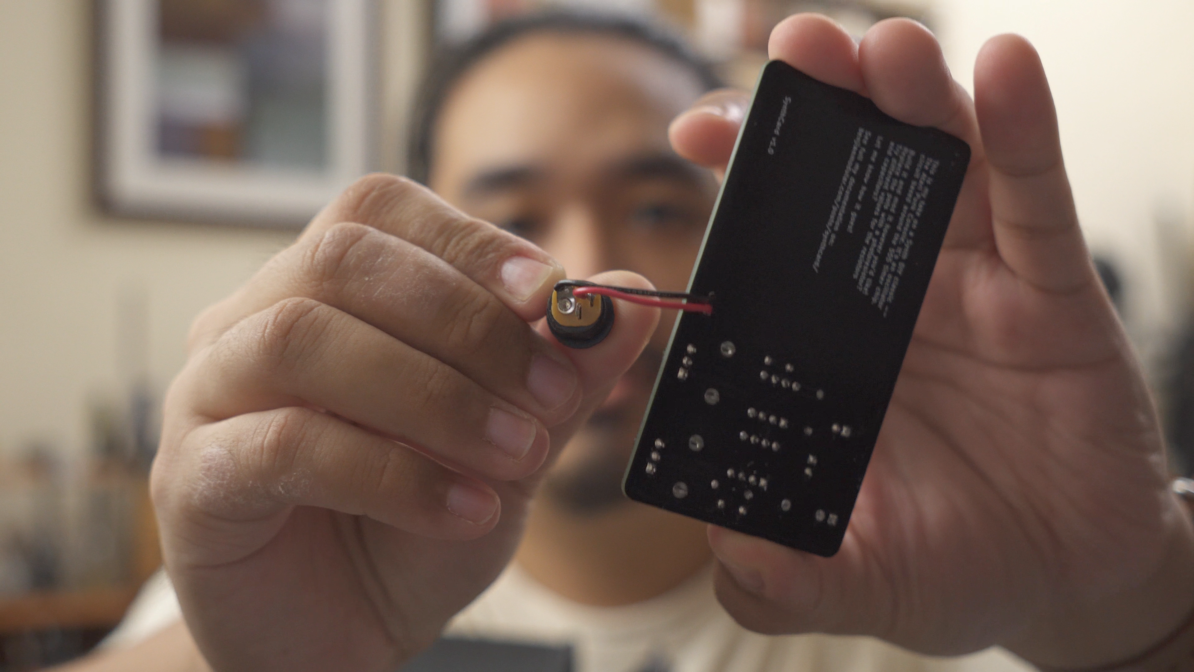
This is my business card for benjiaomodular.com. It is a working oscillator circuit based on the Atari Punk Console. It produces a pulse/square wave at 9Vpp.
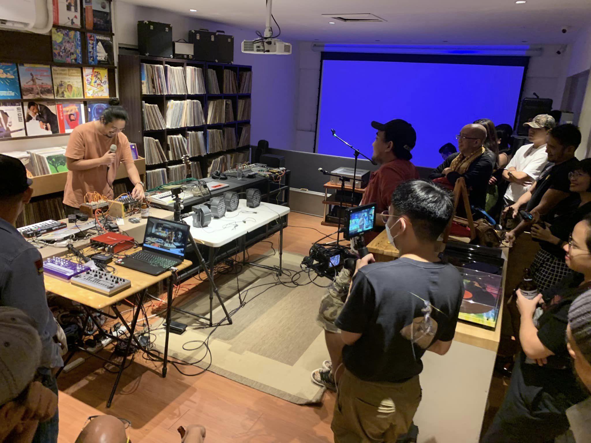
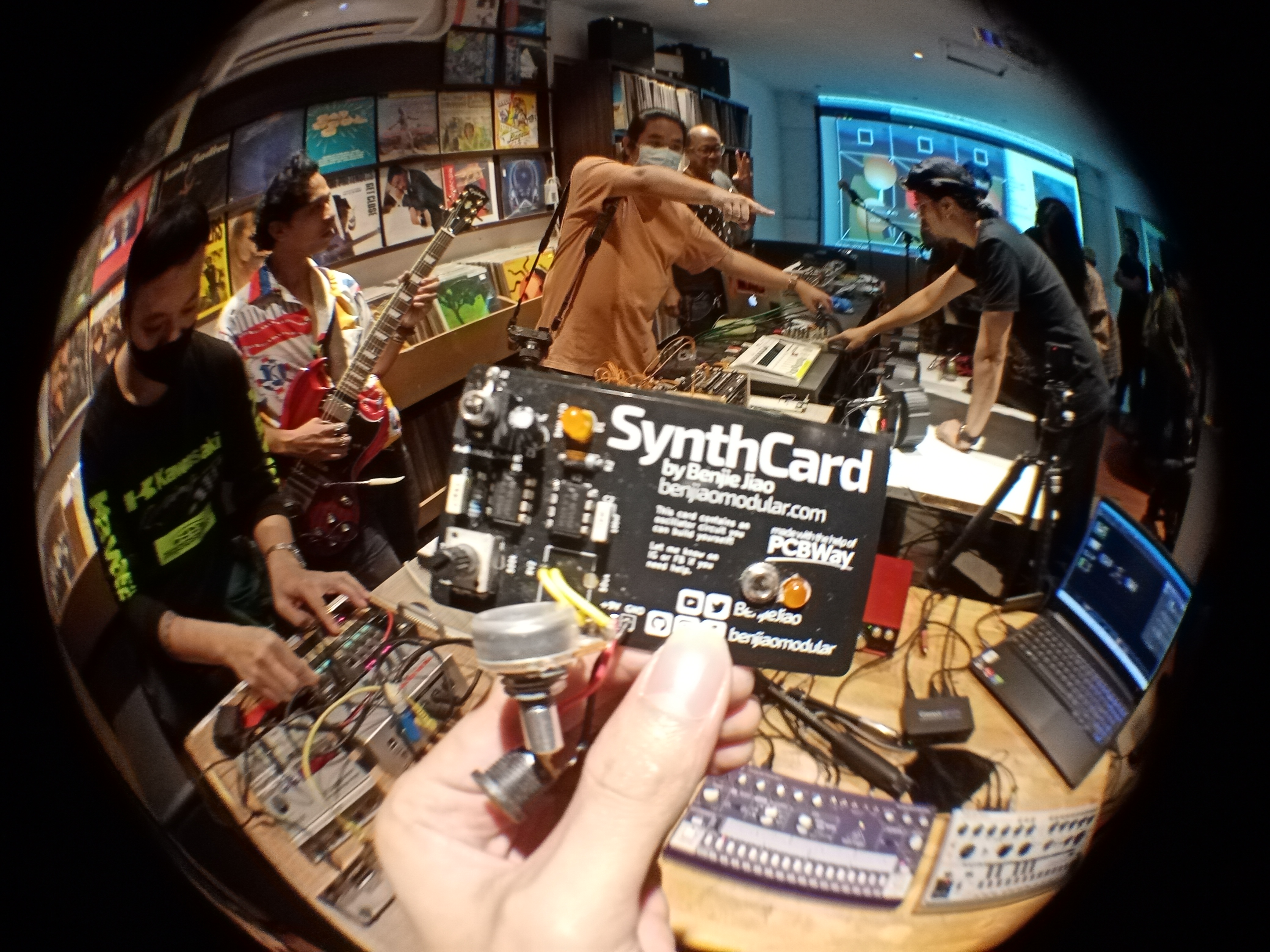
I started this project when Nono (@noel_acosta), founder of the local Philippine Synth Group SYNTHICIDE, invited me to talk about my Synth DIY origins in the group’s SYNC event last November 25.
The group has been very supportive of my Synth DIY adventures online so I wanted to have a little something to give away during the event.
Here are some shots by Jonas Vtxl and Jing Garcia of me and the SynthCard at the event!!
I have seen a couple of circuit-based business cards before, so I thought I’d make one with a synthesizer circuit that people can make on their own. I put together a quick Atari Punk Console PCB on KiCad and approached PCBWay who was nice enough to manufacture the cards for free.
Build
Here’s a short guide on how to build the SynthCard.
Bill of Materials (BOM)
These are the components you’ll need in order to turn this calling card into a pulse wave oscillator. I usually buy from Mouser and, more recently, Tayda.
| # | Value | Type | Part # |
|---|---|---|---|
| 1 | PinHeader | Battery Connector | |
| 1 | 10nF | Capacitor | MMK5103K50J01L4BULK |
| 1 | 100nF | Capacitor | MMK5104K50J01L4BULK |
| 1 | 10uF | Capacitor | UVR1E100MDD1TD |
| 1 | 5mm LED | 5mm LED | |
| 1 | 3.5mm Mono | Jack | PJ398SM |
| 1 | 1k | Resistor | MF1/4DCT26A1001F |
| 1 | 10k | Resistor | MF1/4DC1002F |
| 2 | 500k | Potentiometer | RV09AF-40-20K-B500K |
| 2 | NE555P | Timer IC | NE555P |
Some notes on the BOM
- The power connector can be anything that would let you feed 5-9V power into the SynthCard. I personally use a barrel jack socket (the one used for guitar pedals). You can also use a 9V battery snap.
- I have a list with Lazada links for Filipinos who’d like to order from there.
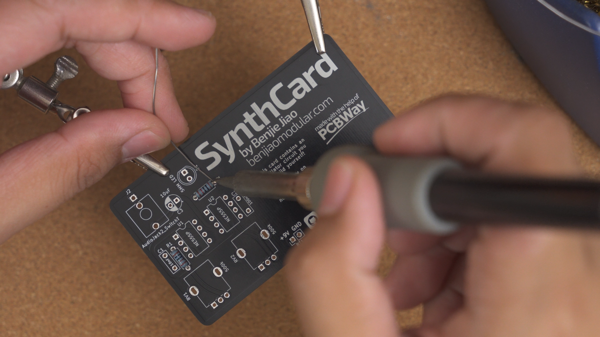
Assembly
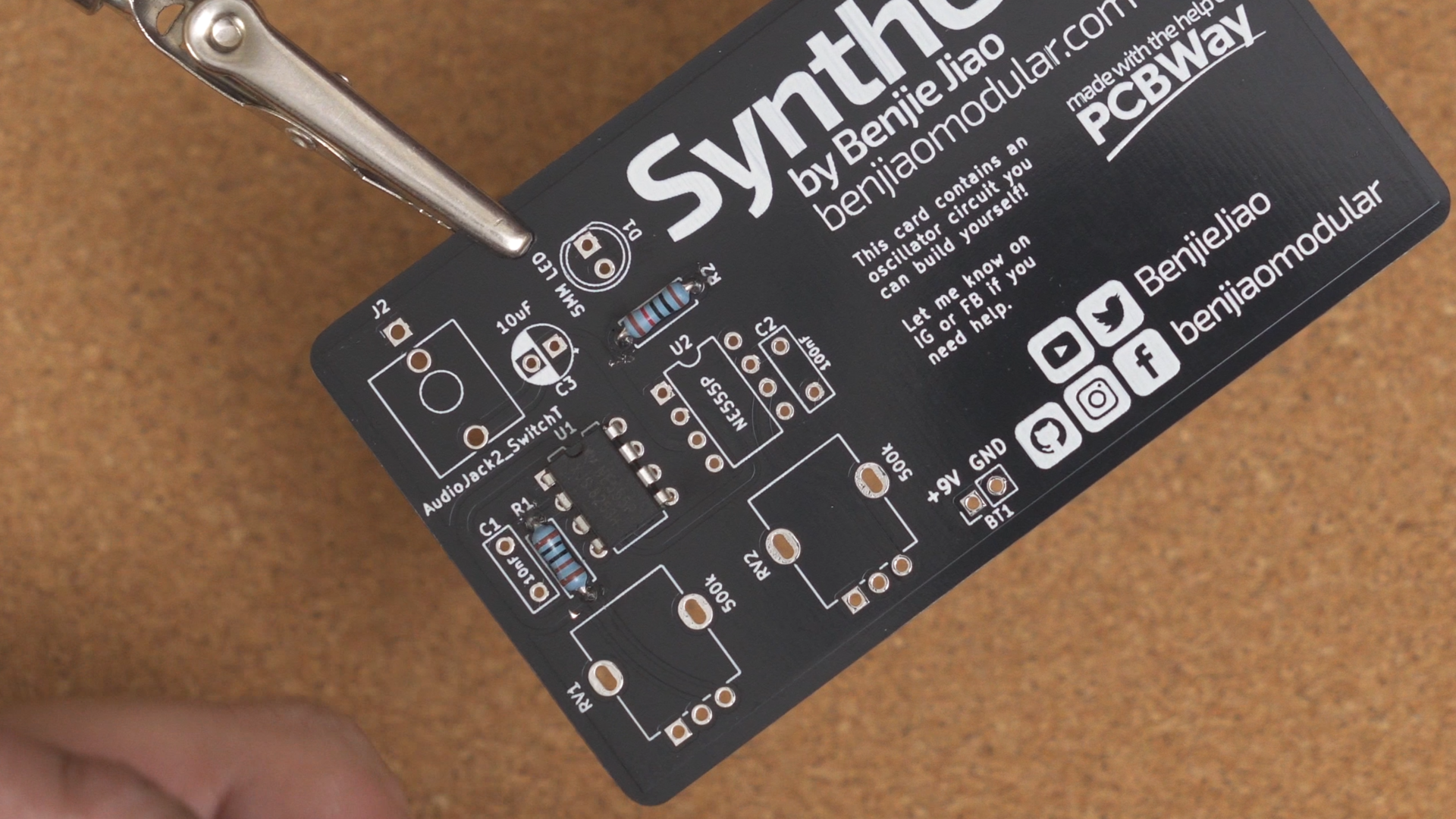
Step 1. The Resistors
It’s a good idea to work on the shorter components first. For most thorugh-hole circuits, these would be the resistors and the diodes. Since the PCB pads are double sided, I like to solder these components from the top.
I don’t show this in my guide video, but snip off the excess leads from the back.
Step 2. The 555 Timer ICs
The 555 timer is next. This has to be soldered on in the correct direction. You’ll have to match the notch on the chip with the notch on the card.
I like to solder one pin from the top of the board, flip it over, and then solder the rest.
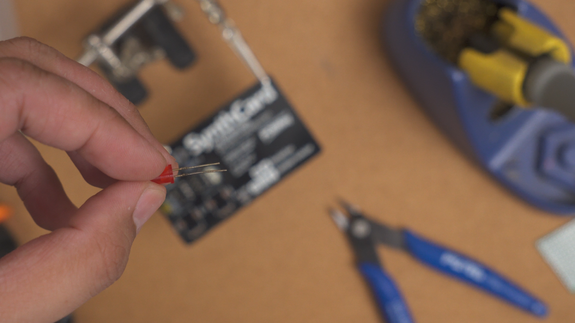
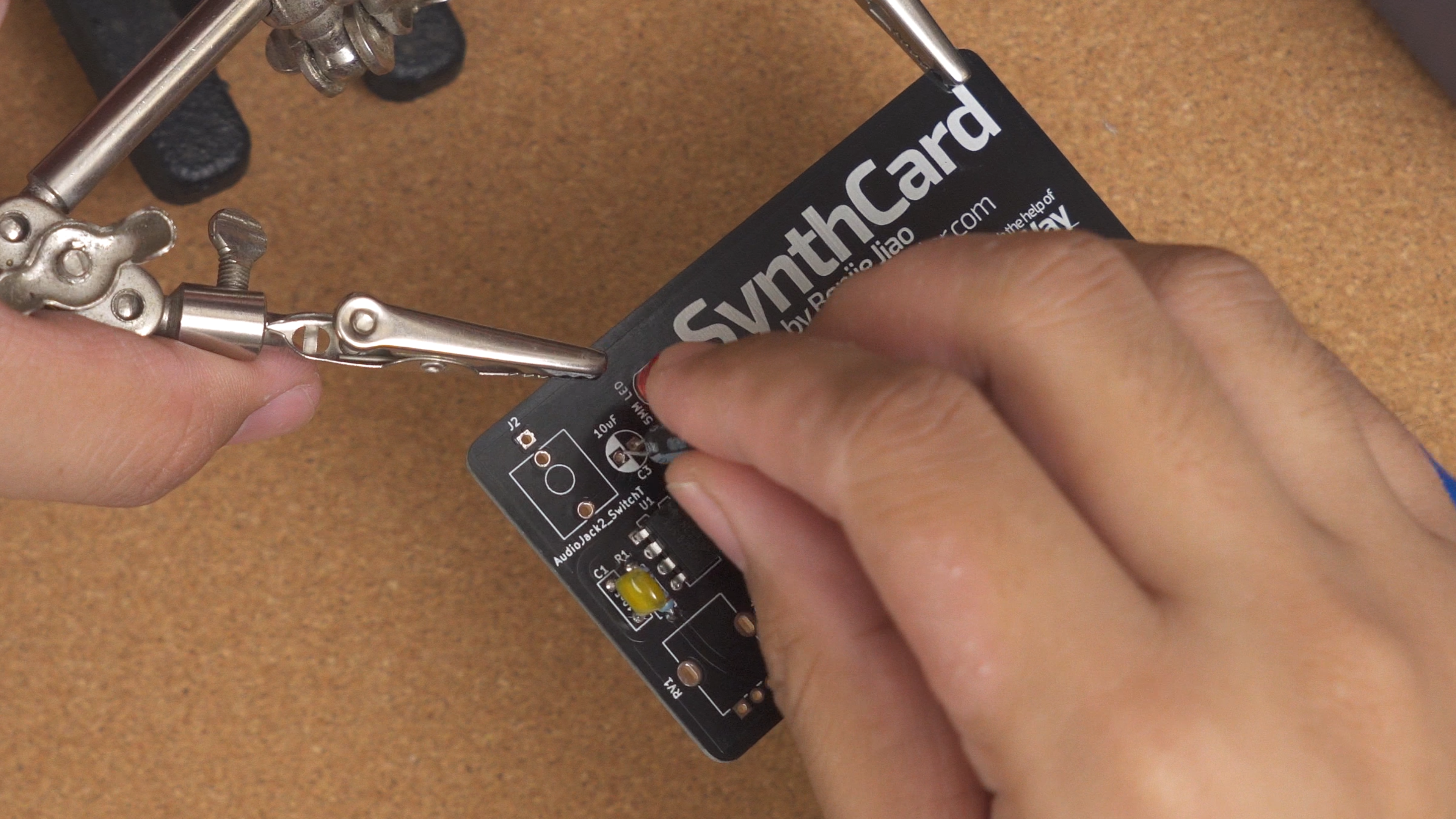
Step 3. The LED
The LED will have a shorter lead. That lead should go into the SQUARE pad of D1. Use tape to keep the LED in place. Solder from the back of the board.
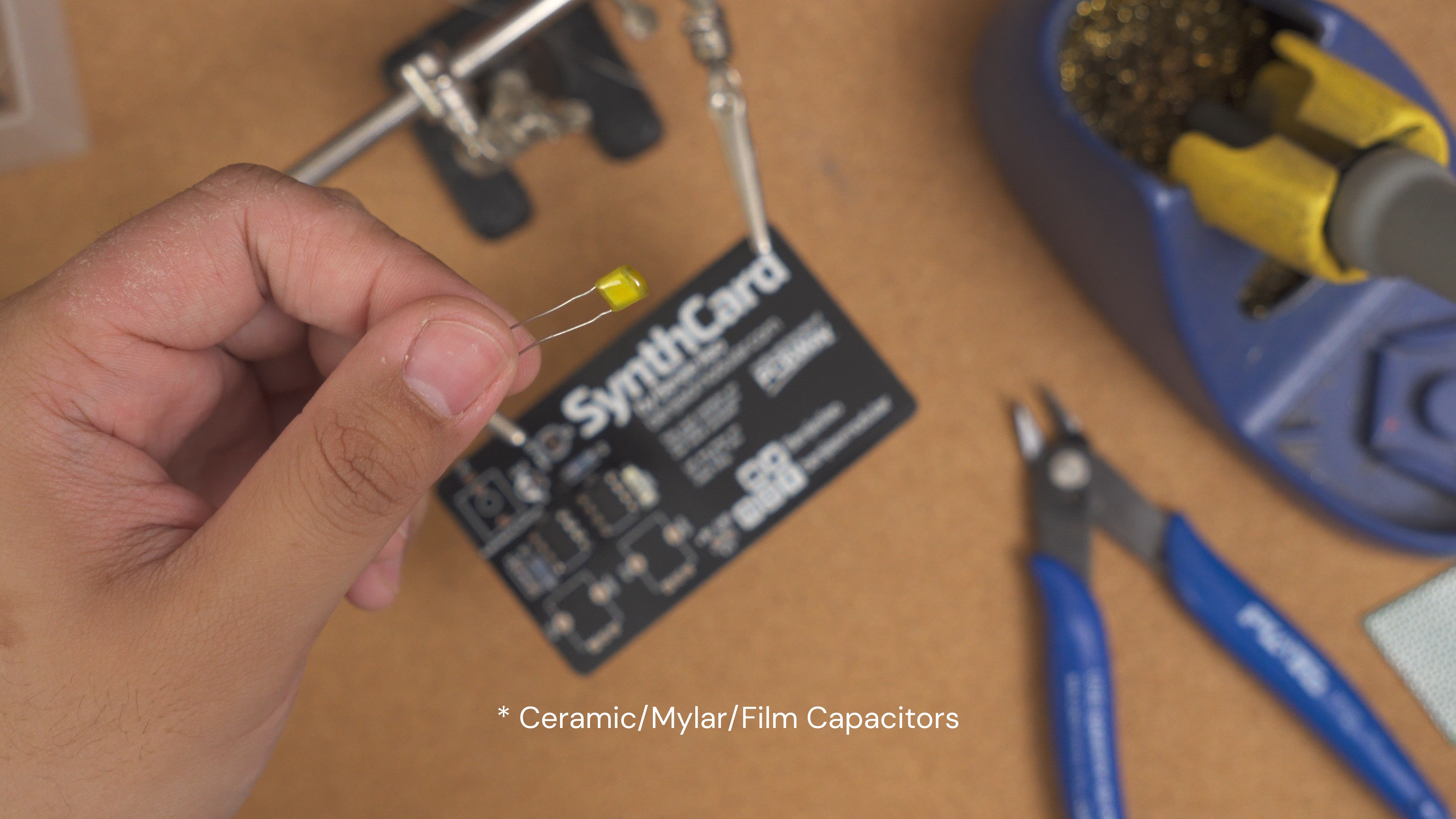
Step 4. The Capacitors
You will encounter two categories of resistors in this build – The non-polarized ones (10nF and 100nF) and the polarized ones (10uF).
The non-polarized capacitors can be ceramic, mylar, or film. These won’t care which orientation you wire them up. I use tape to keep them in place while I flip the board and solder them from the back.
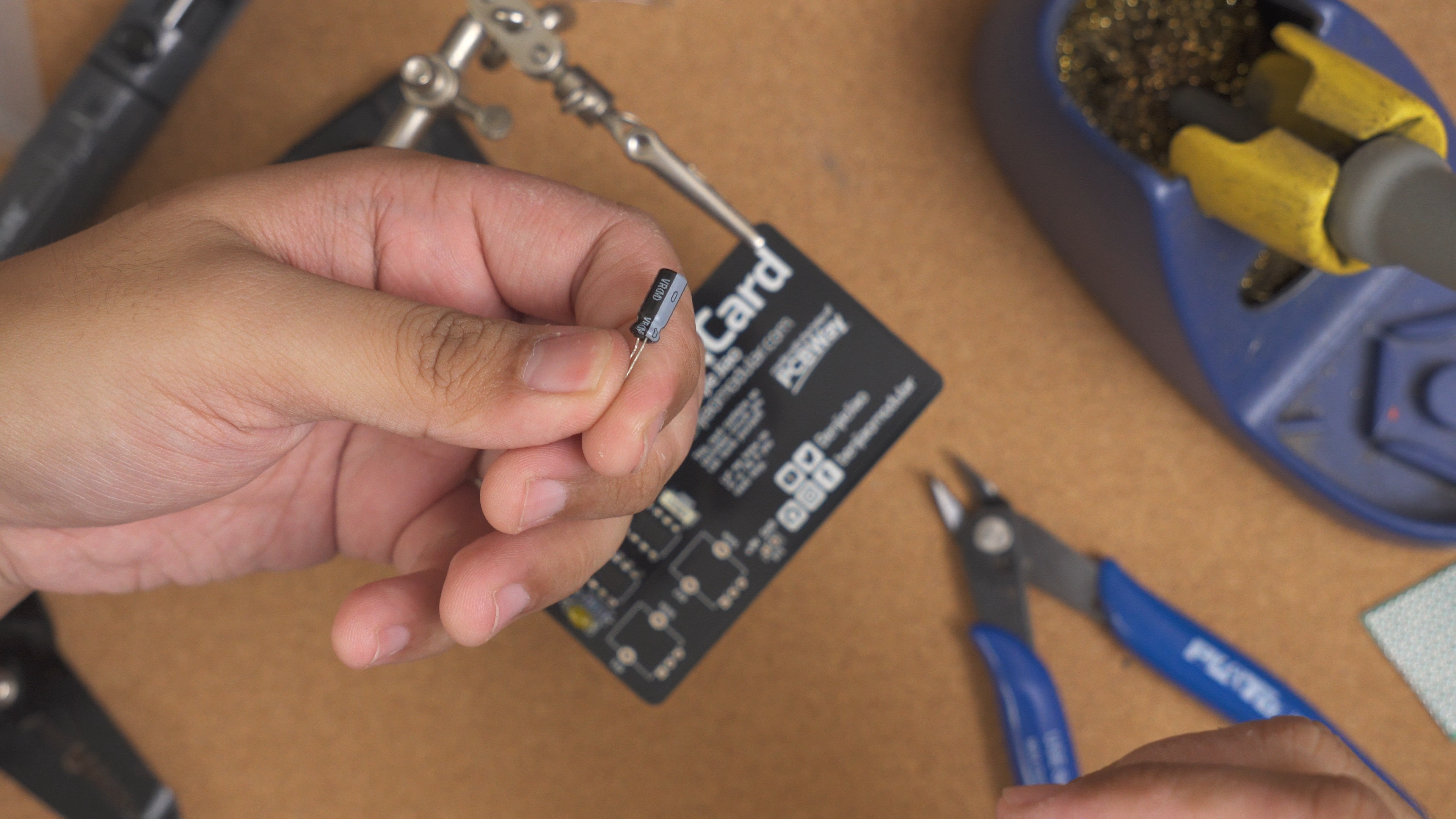
The polarized caps will most likely be electrolytic. These must be solder in the correct orientation. The white strip on the capacitor must be on the shaded (white) side on the board.
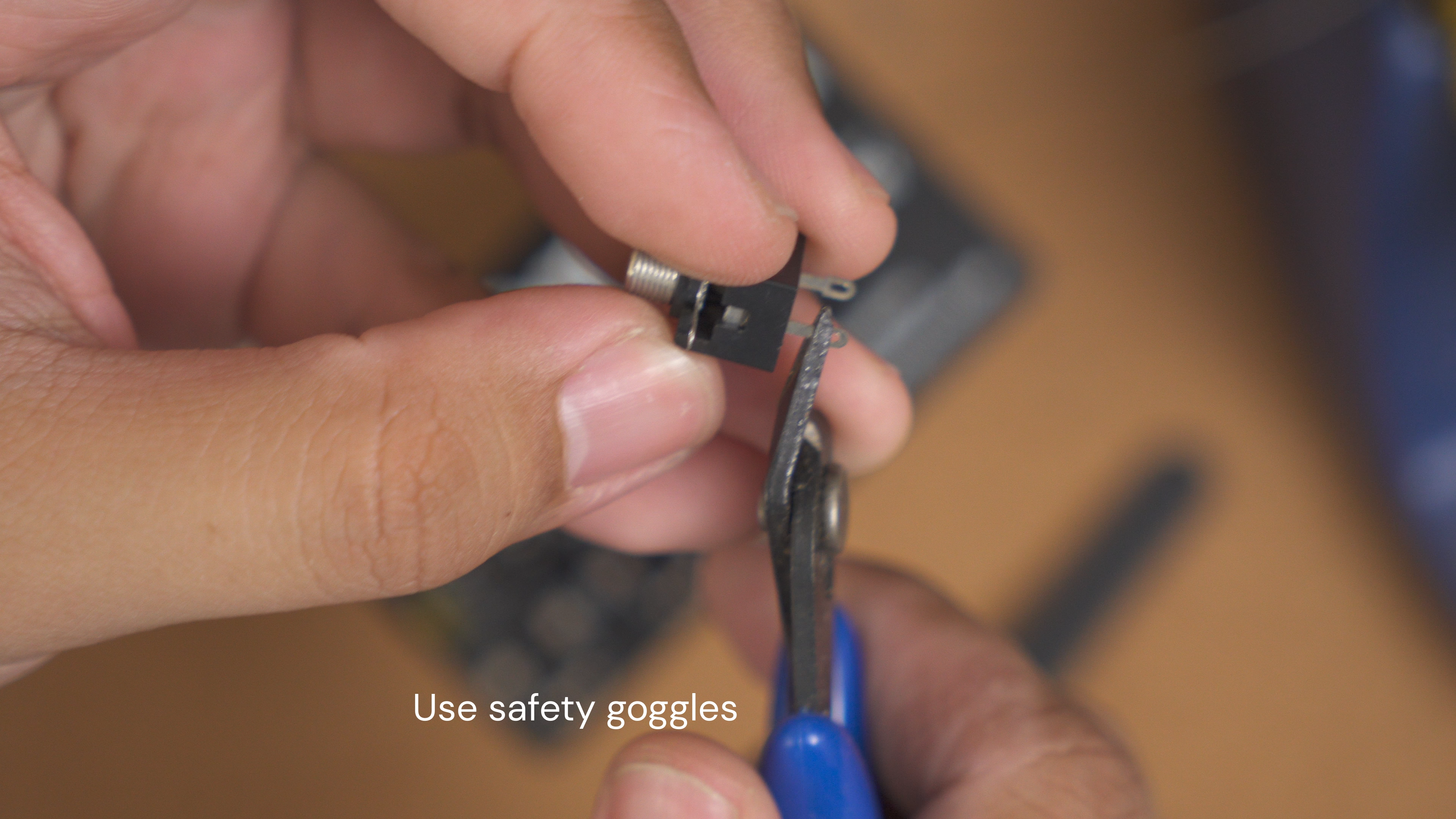
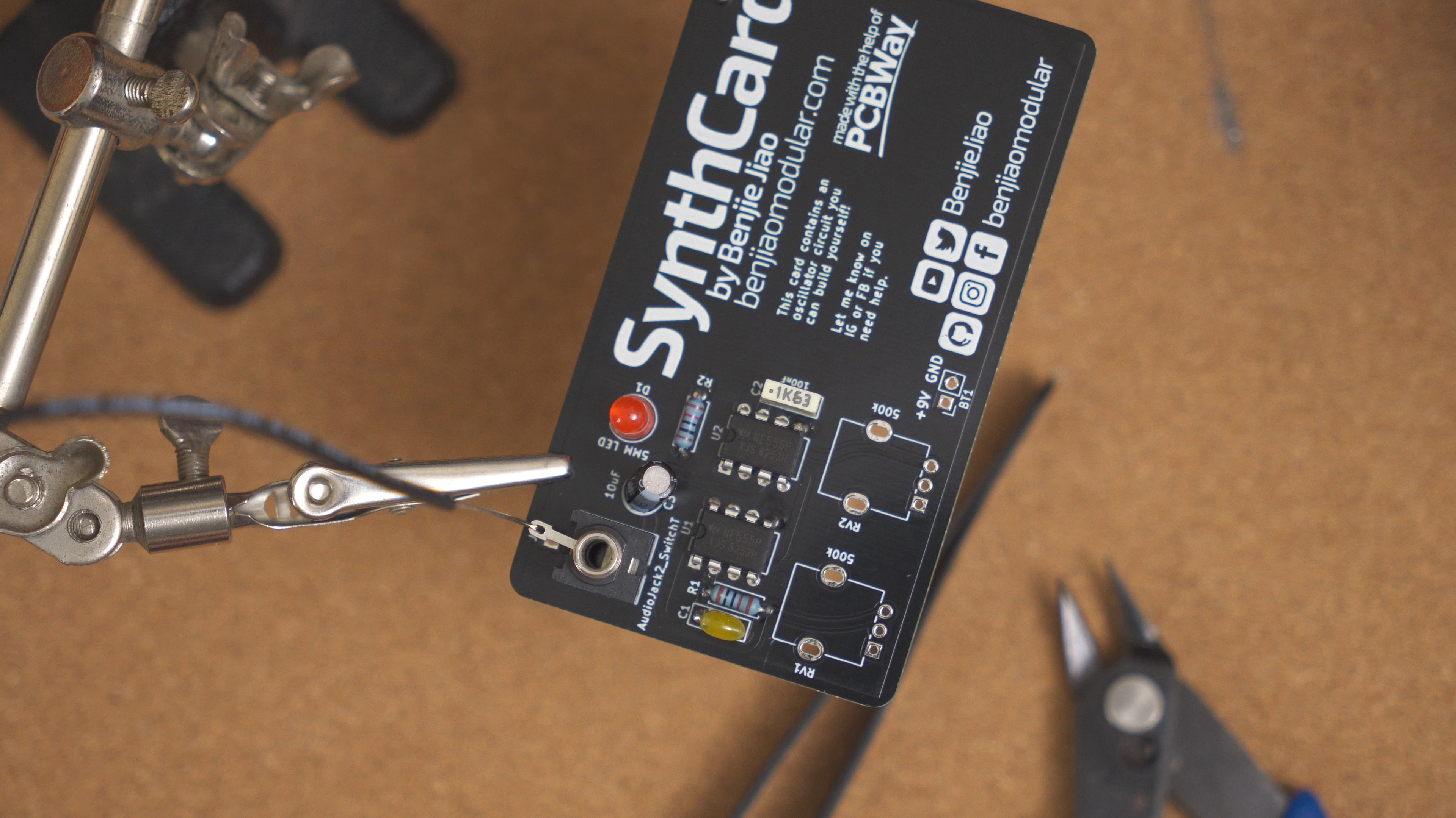
Step 5. The Jack
If you used Thonkiconn jacks, you will only have to line up the ground pin on the square pad on the board, tape it up, and then solder from the back.
I didn’t have Thonkiconn jacks so I had to snip of the wire loops on mine, and then connect the ground pin with solid 24awg wire. Make sure to solder all 3 pins on to the board.
Step 6. The Pots
If you’re using RVO6 pots, they will snap into place. Solder all three pins on to the board. I like to keep the retention arms on the sides unsoldered so I can modify my card easily.
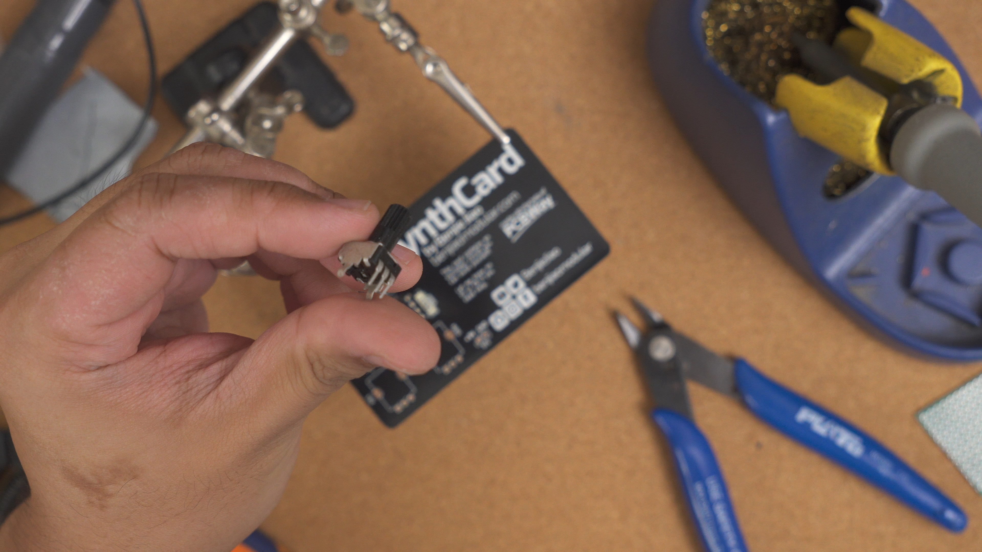
It’s also a fun idea to try out different values for the pots. I recommend starting with 500kohms first, but also try 1k and 1M!
Step 7. Power
The power connections will differ depending on what type you’re using. For my barrel socket connectors, I wanted to wire it up like a guitar pedal so I can plug it into a pedal board.
Wrap it up
Time to see if it works! Make sure to turn your volume down first. Powering this with 9V will give a pretty loud output. Increase your volume gradually.
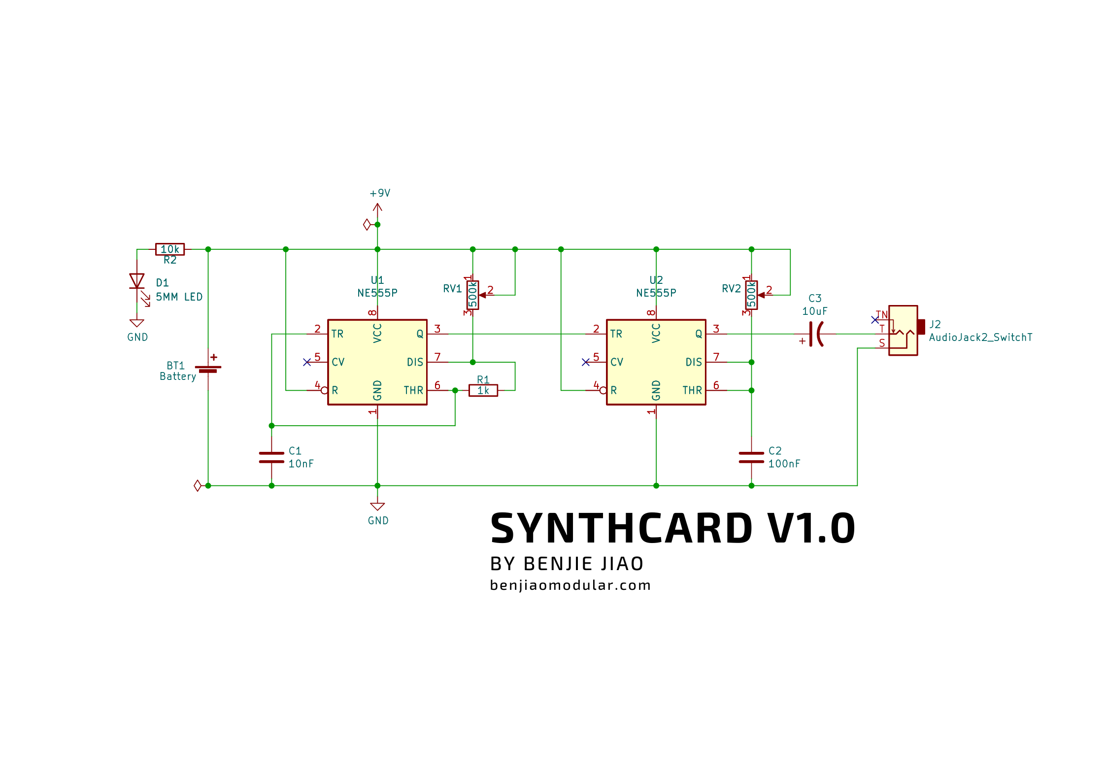
Schematics
This diagram describes how each component in the SynthCard is hooked up together. The identifiers on the board (ie. U1, R1, C1) will match up to the identifiers in the diagram.
PCB
Most PCB shops use Gerber files for etching copper traces, printing lables, drilling holes, and other manufacturing details. You can download my zipped files for a version you like and upload those into their website.
My PCBs for this were sponsored by PCBWay – a great option for prototyping. Use their Quick-order PCB tool to get an instant quote on the files or go to my PCBWay project page to order a copy directly from them.
Versions
v1.0 - Initial version
Confirmed it works with no issues.
| Title | Filename |
|---|---|
| Schematics | SynthCard.pdf |
| Gerber Files | SynthCard v1.0.zip |
Conclusion
As always, this build is fully open source and you can find all my files for this on Github. Feel free to use my files to design your own card!
In hindsight, I could have added M3 screw holes for mounting this build on to a panel or a guitar pedal case. I should do that on future versions.
There are also plenty of modding/circuit-bending opportunities in this build. Maybe fix some light dependent resistors in place of the pots or add a filter circuit at the output?
Let me know if you’ve built it. Tag me on Instagram @benjiaomodular. I also have a couple of demos there!