MiniVCF
Introduction
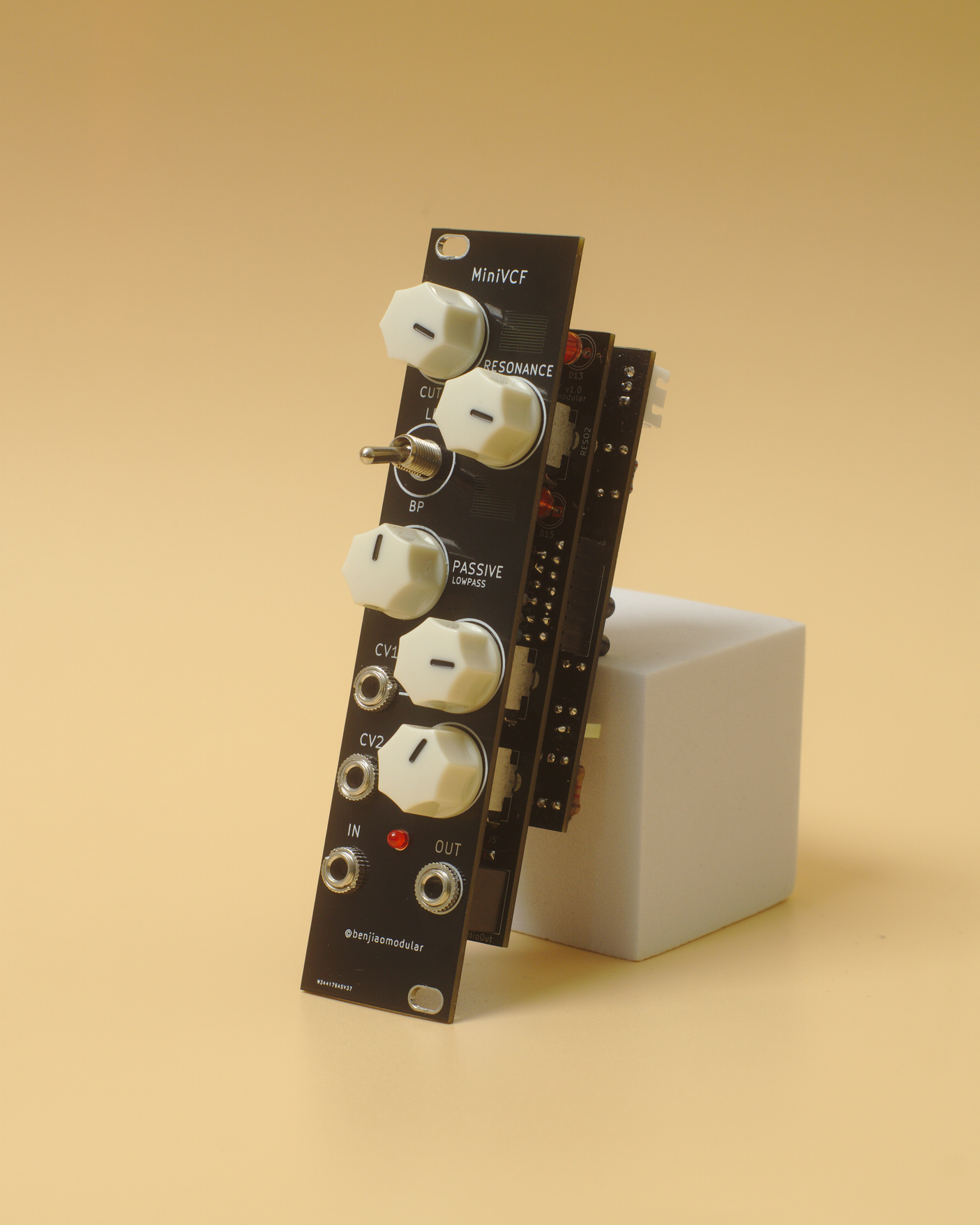
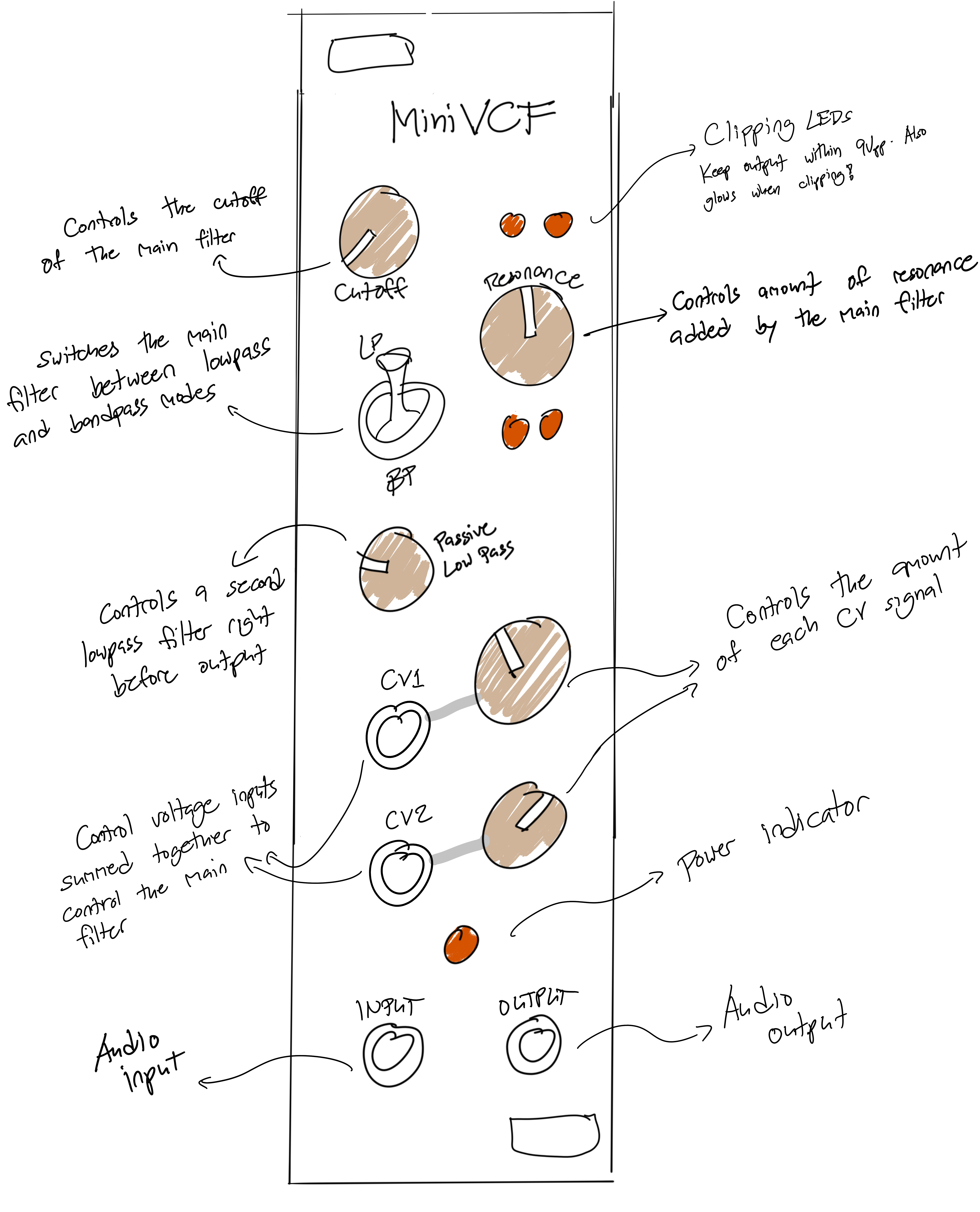
This build is my take on Moritz Klein’s diode ladder design. I added a clipping section and a second filter so you can crank up the resonance while keeping the output at reasonable levels.
The module has a switch for lowpass or bandpass modes.
Build
Bill of materials
| # | Value | Type | Part # |
|---|---|---|---|
| 2 | 1uF | Capacitor | |
| 1 | 680pF | Capacitor | |
| 4 | 1nF | Capacitor | |
| 2 | 100uF | Capacitor | |
| 5 | 100nF | Capacitor | |
| 2 | 100k | Potentiometer | RV09AF-40-20K-B100K |
| 3 | 10k | Potentiometer | RV09AF-40-20K-B10K |
| 11 | 1N4148 | Diode | 1N4148 |
| 4 | 5mm | LED | |
| 1 | 3mm | LED | |
| 1 | JST-XH 1x03 | Socket Connector | |
| 1 | IDC 2x05 | Socket Connector | |
| 4 | 3.5mm Mono | Jack | PJ398SM |
| 2 | Pin Socket | 2.54 pitch, 1x03 | |
| 2 | Pin Header | 2.54 pitch, 1x03 | |
| 2 | Pin Header | 2.54 pitch, 1x07 | |
| 2 | Pin Socket | 2.54 pitch, 1x07 | |
| 1 | Toggle Switch | On-On DPDT | MTS-202 |
| 2 | 200k | Resistor | |
| 8 | 33k | Resistor | |
| 1 | 330 | Resistor | |
| 2 | 2k | Resistor | |
| 3 | 100k | Resistor | |
| 2 | 10k | Resistor | |
| 1 | 2.7k | Resistor | |
| 1 | 1k | Resistor | |
| 1 | 10k-20k | Resistor | |
| 1 | 47k | Resistor | |
| 1 | 200 | Resistor | |
| 2 | TL074 | OpAmp | TL074BCN |
Schematics
Click on the image to zoom in.

The LEDs I used were Red. You can also try out different diodes for the clipping circuit! It could get a bit quieter, but the clipping should sound different. You can probably mod this with a trim pot too.
You can choose the value of R18 based on your preference for the range of resonance knob. I found that 10K gives you a reasonable range, from tame to “just right”. Increasing R18 will give you wilder sounds on higher settings. This will also engage the clipping diodes/LEDs more, giving you more distortion.
PCB
PCB shops use Gerber files for etching copper traces, printing lables, drilling holes, and other manufacturing details. You can download my zipped files for a version you like and upload those into their website.
My PCBs in the MiniSynth series were sponsored by PCBWay – a great option for prototyping. Use their Quick-order PCB tool to get an instant quote on the files.
Check out the PCBWay community page to order the PCBs directly from them:
This build requires three PCBs. Make sure to print all three of them!
Versions
v1.1 - Quick fixes (Unverified)
This version fixes issues found in the initial release.
- Fixed orientation of Cutoff and Post-LPF knobs.
- Updated toggle switch footprint to a bit more space.
- Swapped clipping LED positions. Positive clipping now at the top row.
- Added missing labels for OpAmps, adjusted some unreadable labels.
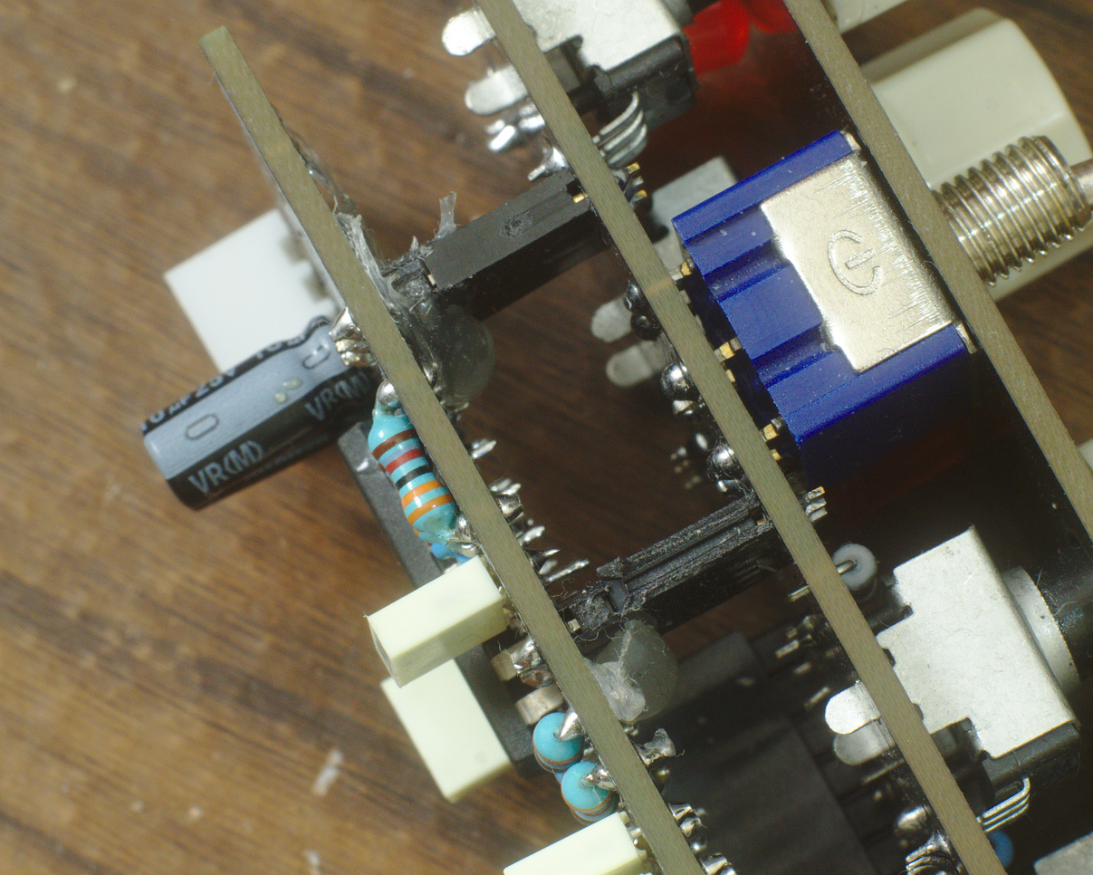
- Issue: Connection between the control board and the main board are a bit loose (seen on the video). Hot glue can be used to secure the boards together.
| Title | Filename |
|---|---|
| Schematics | MiniVCF 1.1.pdf |
| Gerber Files | MiniVCF v1.1 - Main.zip |
| MiniVCF v1.1 - Control.zip | |
| MiniVCF v1.1 - Front.zip |
v1.0 - Initial release
This is the first release of the module. I got it to work, but has a couple of issues.
- Issue: Cutoff and Post-LPF knobs are wired the opposite way.
- Issue: Holes for the toggle switch a bit too tight.
- Issue: Connection between the control board and the main board are a bit loose (seen on the video). Hot glue can be used to secure the boards together.
Some build notes
Connections between panels
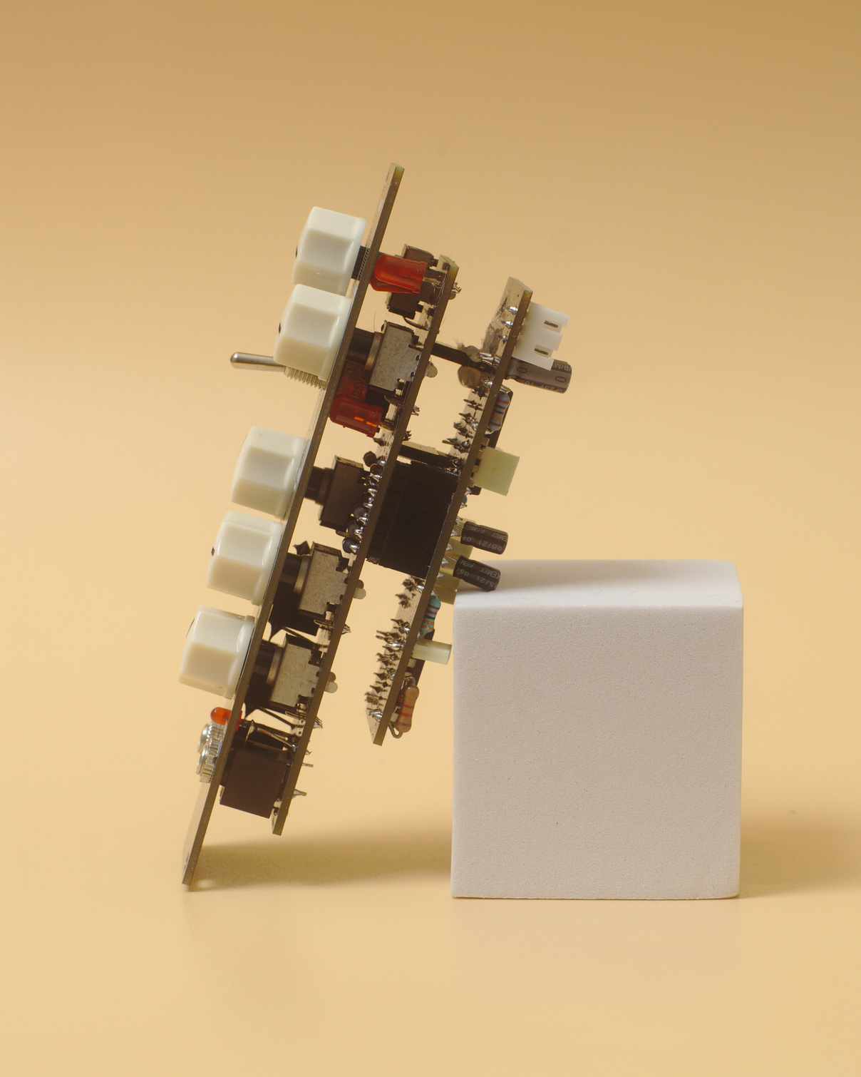
The front panel and the control board are held together by the jacks and toggle switch. I found that this is sturdy enought for normal use.
The control board and the main board, on the other hand, are held together by pin headers.
I made the mistake of not adding mounting holes for a 11mm standoff, as I did in my previous builds. This made the connection between the two boards a bit flimsy. For now, I recommend using hot glue to lock the pin headers and sockets together.
I will fix this in future versions.
Power options
I provided two possible options for powering these boards:
- The first one is a standard 2x5 IDC connector found in most Eurorack modules. This is the one I’d recommend if you already have a Eurorack system.
- The second one is a 3-pin JST header which I use for all my modules. I find the more compact and easier to buy where I’m from.
You’ll only have to pick one to use on your board.
Custom KiCad footprints
I made my own footprint for the RV09-type potentiometers, MTS-202 DPDT swtches, as well as some guide lines for the panels. Download and install it if you wan’t to modify the PCB. You can find my KiCad footprint libraries on Github.
Demos
You can watch my demo and build video of my PCB version on Youtube.
The version featured in the demo was v1.0 with the reversed knobs and other issues mentioned above.
Conclusion
This one is a keeper. I would like to redo the layout to make the board connections more sturdy though. Other than that, I think it’s a great filter.
Other builders have also built this module. Check them out:
Let me know if you’ve built it! Tag me on Instagram @benjiaomodular.