MiniVCA
I’ve been using DIY Vactrols for my Voltage Controlled Amplifiers for the longest time. They’re very easy to build and they work alright.
My problem with them, though, is that their response when doing swells isn’t that good. They would start out quiet then ramp up really quick to max volume.
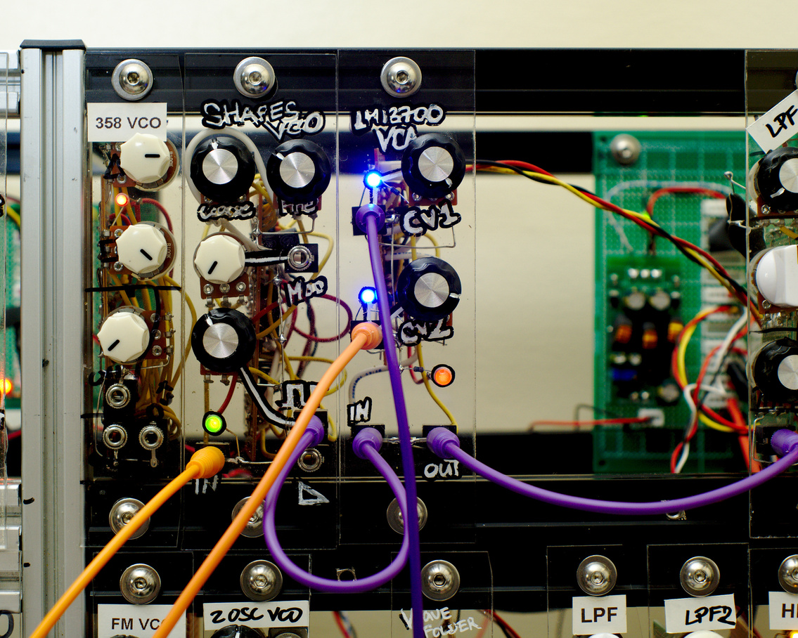
To address this, I decided to upgrade from vactrols to this LM13700-based one inspired by Juanito Moore’s design.
Compared to my LED vactrol VCA’s this one has a more linear response to the CV input which lets me do smoother swells and fades with my ADSR. I also put in a secondary CV input so I can add texture and movement from an LFO.
Here’s a demo with me using a perfboard-prototype of this circuit.
I also have a demo video of the PCB version which includes some assembly steps. I use v1.0 on the video.
Bill of Materials
Here’s a list of what I used in this project. All resistors are 1/4W, electrolytics are 5mm diameter at most, box type caps are 5.00mm pitch.
Passives
- 2 x 100uF capcitor
- 2 x 120pF capacitor
- 4 x 100nF capacitor
- 3 x 10k resistor
- 4 x 20k resistor
- 2 x 100r resistor
- 1 x 47k resistor
- 1 x 680r resistor
- 2 x 100k resistor
- 2 x 3mm LED
ICs and Transistors
- 1 x LM13700 IC
- 1 x TL072
- 1 x BC559
Hardware
- 2 x B100k potentiometers (RV09AF-40-20K-B100K)
- 1 x 8-pin DIP socket
- 1 x 16-pin DIP socket
- 4 x 3.5mm audio jack
- 1 x 2x8 IDC PCB header for power (for standard Eurorack supplies)
- 1 x 6-pin JST PCB header for power (what I use in my system)
If building PCB
- 1 x 1x16 P2.54 Pin Header
- 1 x 1x16 P2.54 Pin Sockets
- 1 x 12mm hex standoff
- 1 x M3 nut
- 1 x 5mm M3 screw
Schematics
This is another straightforward build. You can find the original drawing here.
The weird pin header setup in my schematics is for my PCB layout. I’ve broken down the circuit into two separate boards. You can ignore those and connect the two ends directly if you’re building this on perfboard/stripboard.
Click on an image to zoom.
1 of 2 - The main board - This contains most elements of the VCA circuit.
2 of 2 - Power - This contains the power jacks, some bypass capacitors for the ICs, and some bulk capacitors at the power supply.

This is probably not the most efficient way of doing this as I am only using half of an LM13700 chip. Future modifications might include having two independent VCA’s in the same module.
My KiCAD files are on my Github page. I have some PCBs for this on the way as well. Will be testing those out soon. Follow me on IG @benjiaomodular for updates. Tag me if you’ve built this!
PCB
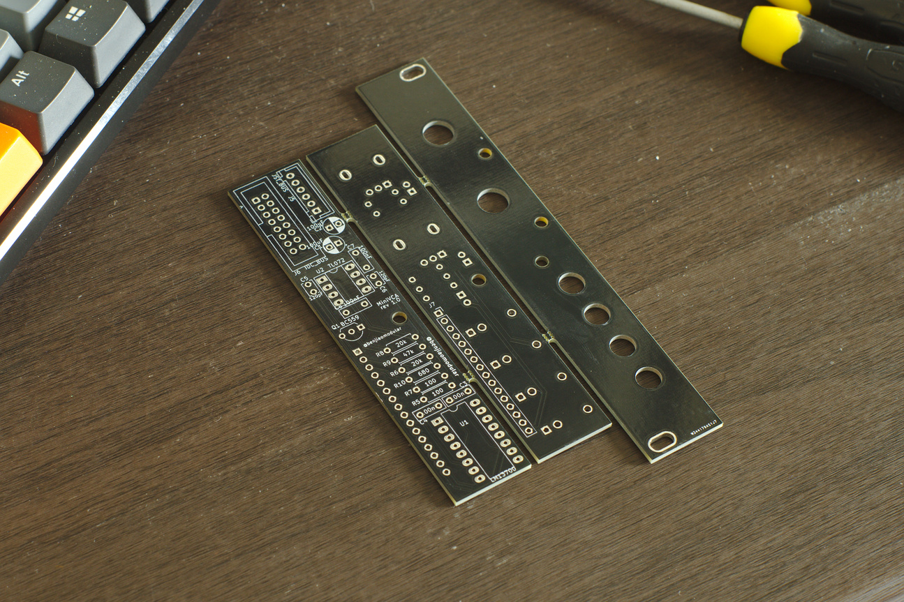
My first run of this was sponsored by PCBWay. Just like with my MiniOSC build, this one is split into three separate board – front, control, and main.
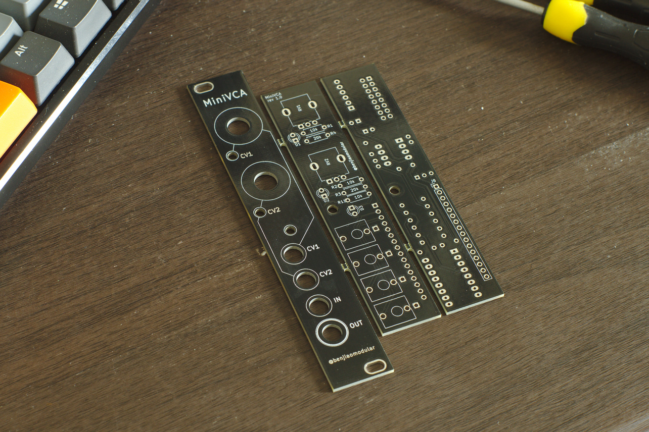
The panels can be snapped off using mousebites and the remaining material can be sanded/filed down flush to the edge of the boards.
Connections between panels
The front panel and the control board are held together by the 3.5mm audio jacks.
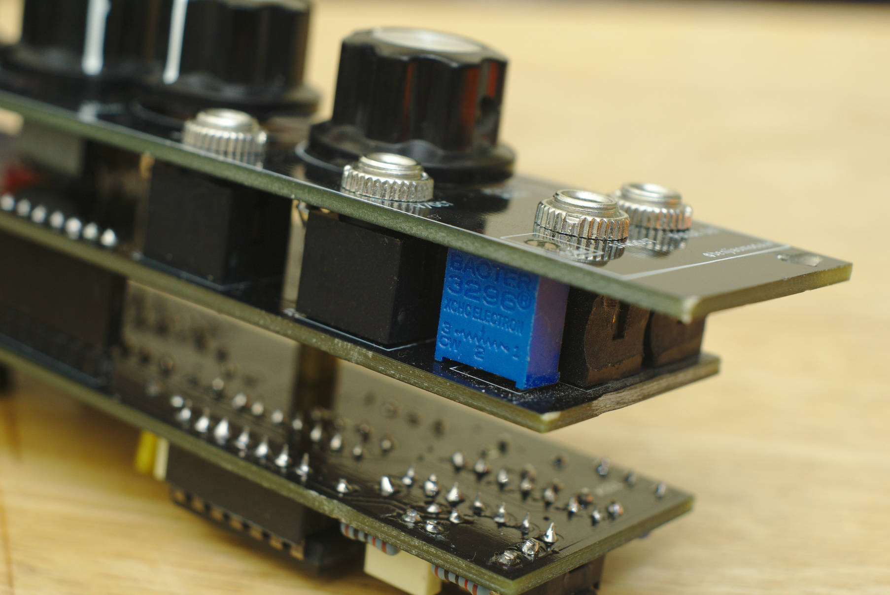
The control board and the main board are coupled at two points: the 12mm M3 brass standoff and the 16-pin headers.
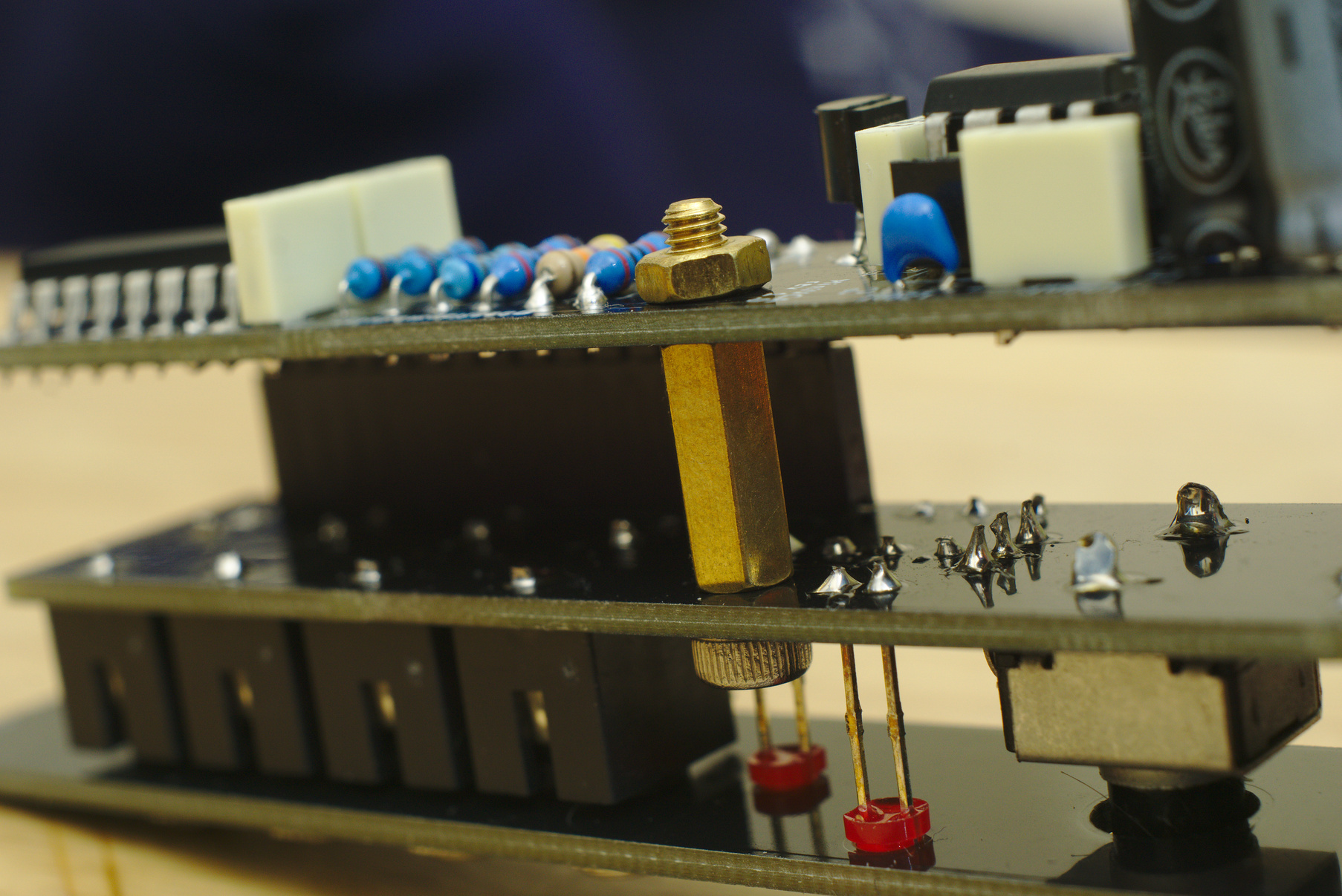
The pins also carry power and audio signals between the two boards.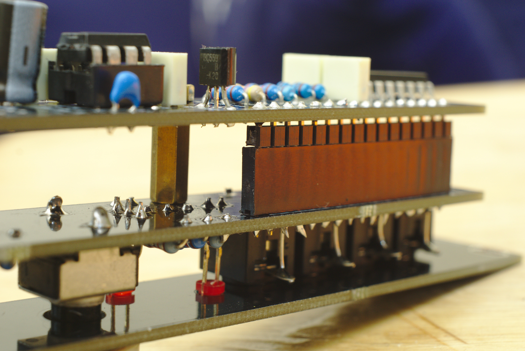
Power options
I provided two possible options for powering these boards:
- The first one is a standard 2x8 IDC connector found in most Eurorack modules. This is the one I’d recommend if you already have a Eurorack system.
- The second one is a 6-pin JST header which I use for all my modules. I find the more compact and easier to buy where I’m from.
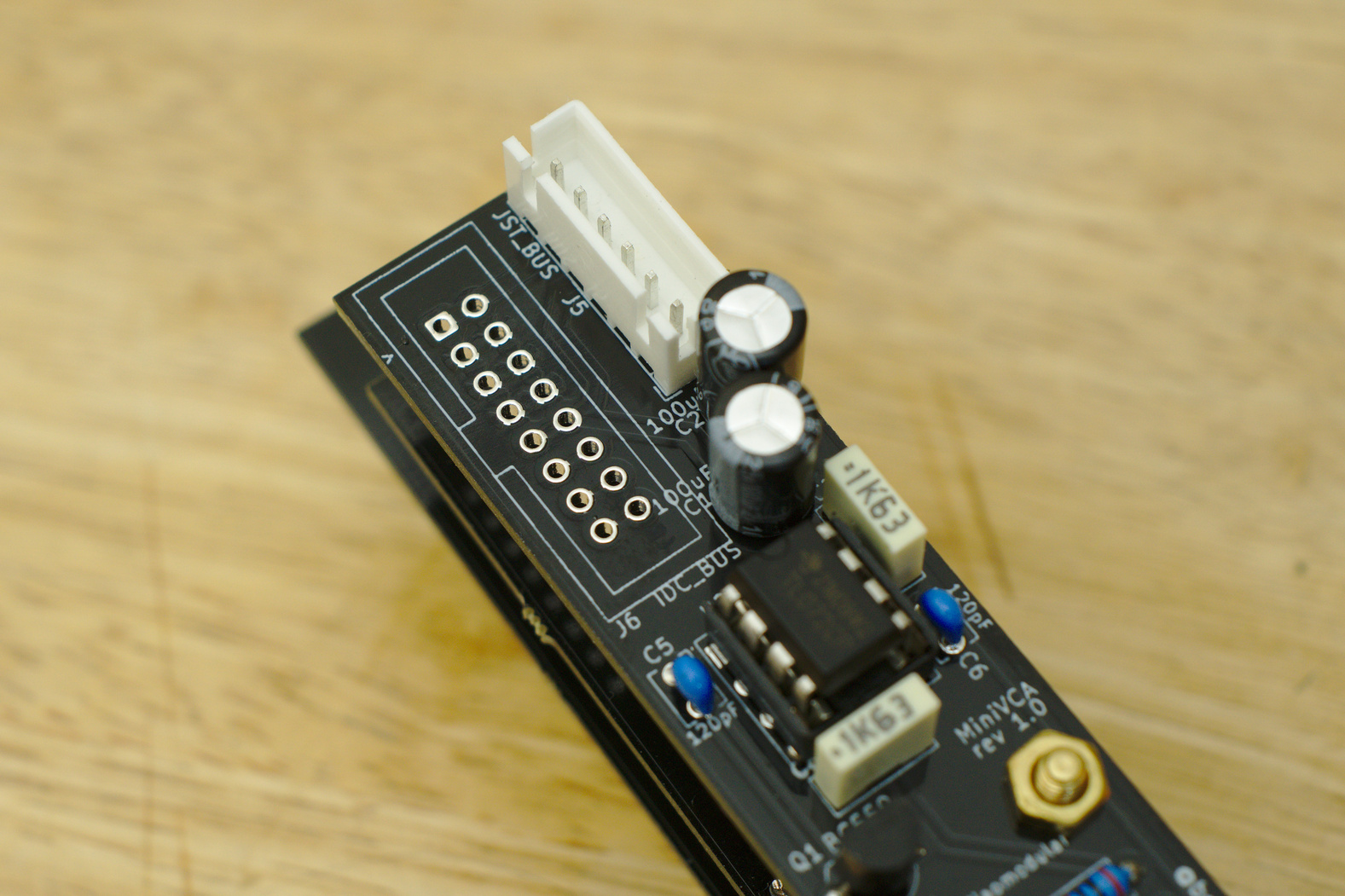
You’ll only have to pick one to use on your board.
Custom KiCad footprints
This was my first time trying out custom footprints for KiCad.
I made my own footprint for the RV09-type potentiometers as well as some guide lines for the panels. You can find my KiCad footprint libraries on Github.
Where to get one
You can order the boards directly from my PCBWay community page. My last print cost me $55 for 5 pieces not including shipping.
You may also download the Gerber files from my Github, or through the links below.
Versions
1.1 - Corrections from first run
Resolved the major issue found in v1.0. Also trying out some label options.
- Fixed the footprint for the LM13700 IC
- All labels on the front panel were moved to the F.Mask layer. I liked the bare copper look better than silk screen.
| Title | Filename |
|---|---|
| Schematics | MiniVCA 1.1.pdf |
| Gerber Files | MiniVCA 1.1.zip |
1.0 - Initial release
This works, but with a minor issue with the LM13700.
- [Issue] I used the wrong footprint for the LM13700. The one I used was too wide. I wasn’t able to use an IC socket, but I was able to get it to work by bending the LM13700’s pins until they go through the holes.
| Title | Filename |
|---|---|
| Schematics | MiniVCA 1.0.pdf |
| Gerber Files | MiniVCA 1.0.zip |
Featured builds
Other makers have built this circuit themselves. Check them out:
Let me know if you’ve built it! Tag me on Instagram @benjiaomodular.